~
~
,
~
..
~
.
•
•
I
!
'
x
=
3
,
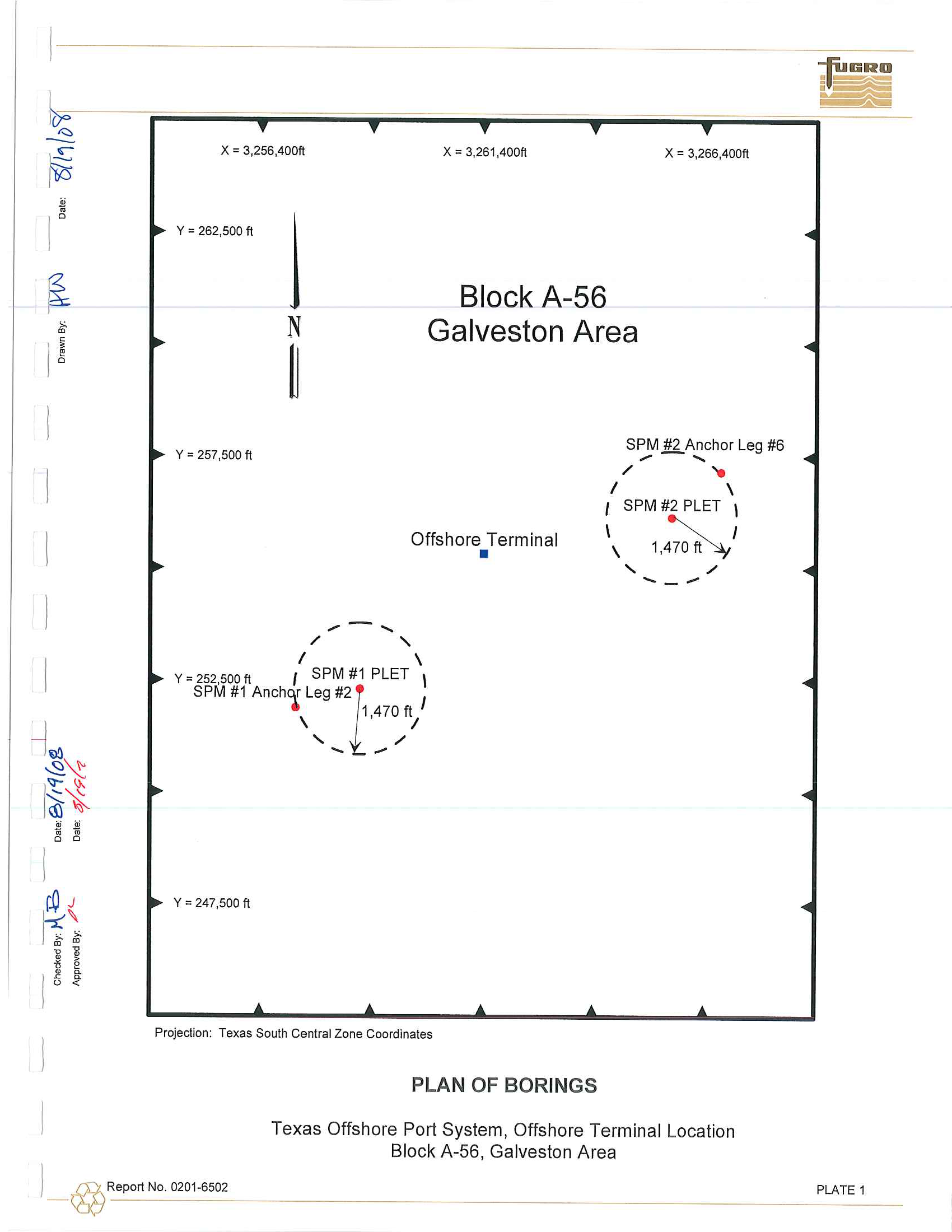
256,400ft
x
=
3
,
261
,400ft
x
=
3
,
266,400ft
~
'"'
'"
I
I
1
~
~
~
1
'<3-
IX
~
~
~
2
o
~
~
~
I
~
Ii
'"
I
~
K
"
:t
Y
=
262
,
500
ft
Y = 257,500
ft
N
~
...
-
.....
;'
"-
Block A-56
Galveston Area
Offshore
Terminal
•
SPM
#2
Anchor
Leg
#6
...
-
.....
/
....
I
\
I
SPM #2
PLET \
\
~
I
,
1,470
ft~
"-
;'
.... _ ....
I
\
Y
=
252
,
500
ft
I
SPM #1
PLET \
SPM
#1 Anch
l
Leg
#2
[
I
,
1,470ft
l
"-
""
;'
.... I.... ...
Y
=
247
,
500
ft
Projection: Texas South Central Zone Coordinates
PLAN OF BOR
IN
GS
Texas Offshore Port System, Offshore Terminal Location
Block
A-56, Galveston Area
I_
@
Report
No
.
0201-6502
PLATE
1
1
@
G'
"
o
;J.
o
Z
o
'"
"<
&,
'"
o
N
~
~
...:
o
'iii
(]J
(fJ
~
Qj
en
c
g
~
ill
c
(]J
(L
-u
~
m
N
ID
Chec""u
uy.
I/-w
D..
,,,,.
-
/'
g<'jlf."
-v
J'~~~~
__
__
====~~~
Drawn B .
'Pn
~'te,
g
/1>
,~,
Approved By:
4Jh
Date:
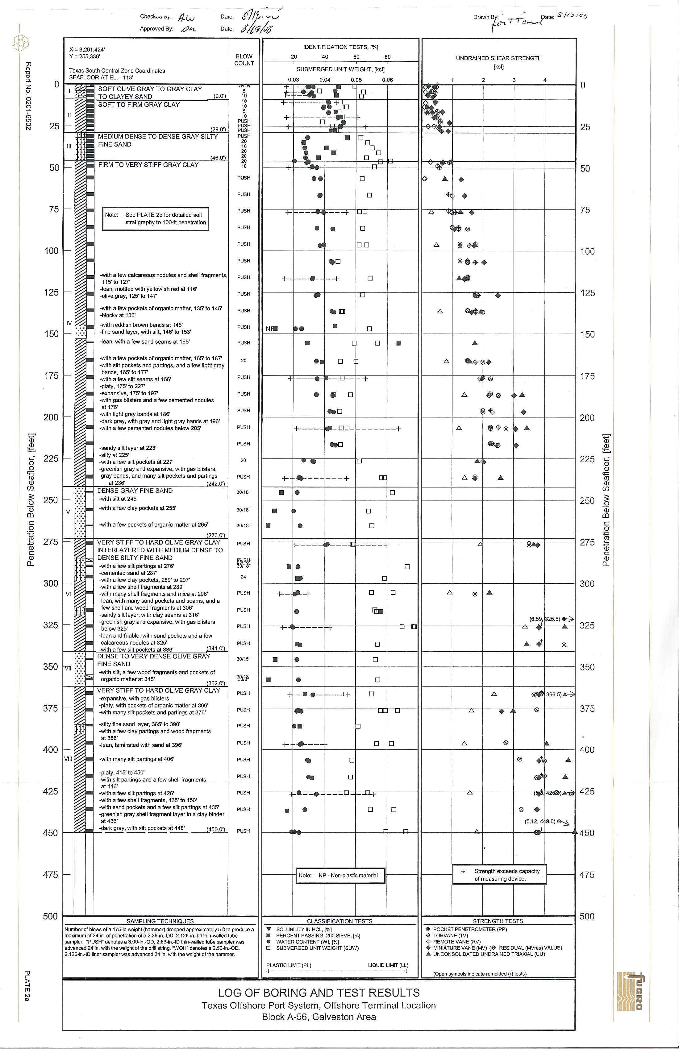
x=3,261,424'
Y
=
255,336'
Texas
South
Central Zone Coordinates
SEAFLOOR AT
EL -
118'
o
SOFT OLIVE GRAY TO GRAY CLAY
TO CLAYEY SAND
..illD..
25
"
lU
I
50
~
75
I-
100
I-
125
I-
I
IV
150
I-
175
I-
200
I-
2251-
,
I""
,
,
..
i
SOFT
TO FIRM
GRAY CLAY
~2.9
·_9'1
~
DENSE TO DENSE GRAY SILTY
FINE
SAND
_H6.9.')
FIRM TO
VERY STIFF GRAY CLAY
Ol:
See PLATE 2b for
detailed
soH
stratigraphy to
l00-fl
penetration
H
c
-with
a few calcareous
nodules
and shell fragments
~
11S'to 127'
-It:dn, mottled with yellowish red a1116'
-olive gray,
125'10
147'
H
-with a few pockets of organic matter, 135'
to
145'
~
-blocky at 136'
-with
red
d
ish
brown bands at 145'
-fine
sand
layer,
with silt, 146' to 153'
H
-lean,
with
a few sand seams at
155'
~
-
w
it
h
a few
pockets
of organic
matter,
165' to
187'
-with silt
pockets
and partings, and a
few light gray
bands, 165' to 177'
-with
a
few silt seams at 166'
-platy, 175'
to 227'
-expansive, 175'
10
197'
-with gas blisters and
a
few cemented
nodules
at 176'
-
with
light gray bands at
1
B6'
-dark gray, with gray and
light
gray
bands
at 196'
-with
a
few
cemented nodules below 205'
-sandy
silt layer at 223'
-silty at 225'
-with
a
few silt pockets at 227'
-greenish gray
and expansive, with gas blisters,
gray bands, and many silt pockets and partings
at
236
'
(242.0')
:.:
.:
DENSE GRAY FINE SAND
250
I- .
'
.
-with silt at 245'
I
V
.,
-w
ith
a few clay pockets at 255'
275
300
~
3251-
-with a few pockets of organic matter at 265'
273.0'
VERY STIFF
TO
HARD OLIVE GRAY CLAY
INTERLAYERED
WITH MEDIUM DENSE
TO
DENSE
SILTY FINE SAND
-with a
few
silt partings al 276'
-cemented sand a1287'
-w
ith
a few clay pockets, 289'
to
297'
-with a few shell fragments at 289'
-with many shell fragments and
mica
at 296'
-lean,
with
many sand
pockets
and seams, and a
few shell and wood fragments at 306'
-sa
ndy
silt layer, with clay seams at 316'
..greenish
gray and expansive, with gas blisters
below
325'
-
lean
and friable, with sand
pockets
and a
few
calcareous nodules at 325'
-with a
few silt ockets at 336'
341.0'
350
rn
'
-:-:'C
.
JSE TO VERY DENSE OLIVE GRAY
FINE
SAND
-with
silt, a few wood
fragments
and pockets of
organic matter at 345'
~
375
I-
400
I-
IVIII
4251-
450
4751-
O
VERY STIFF
TO HARD
OLIVE GRAY CLAY
-expansive,
with
gas blisters
-p
laty,
with
pockets
of organic matter at 366'
-with
many silt pockets and
partings
at
376
'
-with
a few
clay
partings and wood fragments
at 386'
~
-silty fine
sand
layer,
385' to 390'
-lean,
lam
inated
with sand at 396'
-with many silt partings at 406'
-with silt partings and a
few
she
ll fragments
at416'
~
-platy, 415' to 450'
-with a
few silt partings at 426'
-w
ith
a few shell fragments, 435' to 450'
-with sand pockets and a
few silt partings at 435'
-greenish
gray shell fragmenllayer
in
a clay binder
al436'
f'f'4""'I
-dark
gray, with silt
pockets
at 448'
...i
450.O")
BLOW
COUNT
5
10
10
10
5
10
PUSH
PUSH
PUSH
PUSH
20
1
0
20
20
20
10
PUSH
PUSH
PUSH
PUSH
PUSH
PUSH
PUSH
PUSH
PUSH
PUSH
PUSH
20
PUSH
PUSH
"PUSH
PUSH
PUSH
20
PUSH
30/18"
30/16"
30/18"
PUSH
f!il'l!'
30/18"
24
PUSH
PUSH
PUSH
PUSH
30/15"
'JIIIB'"
PLOH
PLOH
PUSH
PUSH
PUSH
PUSH
PUSH
PUSH
PUSH
NIII
IDENTIF
ICATION TESTS
,
[%]
20
40
60
80
SUBMERGED UNIT WEIGHT, [kef}
UNDRAINED SHEAR STRENGTH
~,ij
0.03
0.04
0.05
0.06
2
3
4
4=
~O
B
+
+
•
'!
•
•
..
r.
•
O~oo
••
•
+r--'
•
..
++--
....
•
~.
•
••
r-'
•
o
o
--+
I
UU
•
10
_0
,
_-+
,
.
[]
•
o
1
0
_
0
o
10-
o
[
---bJ--I-+
II
0
o
•
•
~
F ...
•
<1\
•
A
"t:®.
b.
b.
b.
§~
®@I<I>
....
...
~Ai
...
&'<1>,.
~®
•
b.
~®
...
o
25
50
75
100
125
150
175
II
1..
0
1
II
'~I·
1
1200
"0
b.
I@<I>®~'"
$*
~
+--
--i
--ldld
-
f-
----+--+
I
+J:-~l--+
1
0
~
I I
b.:t
...
I
I
1
225
•
I
.
o
t----j-
-
--t--
-
----I
t---+------111
I
250
•
o
•
•
o
~
•
:J
:j:
.
II
~
I!IAJ
I
\275
o
I
.1:
1
1
~
II
I
300
o
o
A
®''''
IllII
I
"
o
1
+-t+
~
1
-I
I
I"
(6~13255)~1325
~.
+f=+-~
---r-' I
uO
all
u
I
...
+
1
®
o
I • I.
II
I
350
•
•
o
4
-
....... +--"1-
I
0
b.
....
1-
oqo
f>.
•
"
375
•
p
I
+t
....
--t
1
0
1
0
II
1
b.
1
®
1
®
J
...1
400
-
o
..
o
~'*
...
:J:.
.4
0
1:rJ+
I
"
Li
I
(,.;1.,,,,,,...-&1
425
®
•
(5.12. 4t9.0)
&,;,.
~-~
....
o--_+--+_--Qlr-bj.glll
A
I
IITI
4-450
•
•
o
o
1
I
:
1
II
+
St,eo,th meed, "p,,;ty
--1
475
f---
-
~~I
Not"
N~'
NOO'P'''': m,te,;,1
\\
of me",,;o,
de'
;c
e.
I
500
Number of blows
ofa
175-1b
weight (hammer)
dropped
applu""",m:,y;", IU P'UUU'-'''
i:I
maximum
of
24
i
n
.
of
penetrati
on
of a 2.25-in.-OD, 2.125-in.-ID
thin
-walled
tube
sampler.
'PUSW
denotes a 3.00-in
.
-OD, 2.63-in.-tO thin-waned
lube
sampter was
advanced 24 in. with the weight of the drill Strin9.
"WOH"
denotes a
2.50-
i
n.-OD
,
2.l25-in.-lD liner
sampler was advanced 24 in. with
the
weight of the hammer.
SAMPLING
TECHNIQUES
II
.
CLASSIFICATION
TESTS
STRENGTH TESTS
I
500
I
T
SOLUBILITY IN
HCL,
[%)
@
POCKET PENETROMETER (PP)
•
PERCENT
PASSING
-200
S
tE
VE,
[%J
$
TORVANE (TV)
•
WATER CONTENT
(W).
[%)
¢
REMOTE
VANE (RV)
o
SUBMERGEDUNITWEtGHT(SUW)
•
MINIATVREVANE(MV)
(~
RESIDUAL(MVreslVALUEj
PLASTIC
LIMIT
(PL)
+
LIQUID LIMIT (LL)
+
.....
UNCONSOLIDATED
UNDRAINED
TRIAXIAL (UU)
(Open symbols
indicate
LOG OF BORING AND TEST RESULTS
Texas Offshore Port System, Offshore Terminal Location
Block A-56, Galveston Area
~
~
~-
o
'iii
(]J
(fJ
:;:
o
Qj
en
c
o
~
ill
c
(]J
(L
I
@
I
!
o
"
z
?
o
'"
01
in
'"
o
'"
'm
~
o
.:
o
<=
I1l
tV
(fJ
:;:
a;
o
co
c
o
~
ill
c
tV
[L
'1J
~
'"
0-
Chac"'t:... CoIy.
Approved
By
:
~
,0.
Dc"""
Date:
31lf.
~v·
(//<7
4
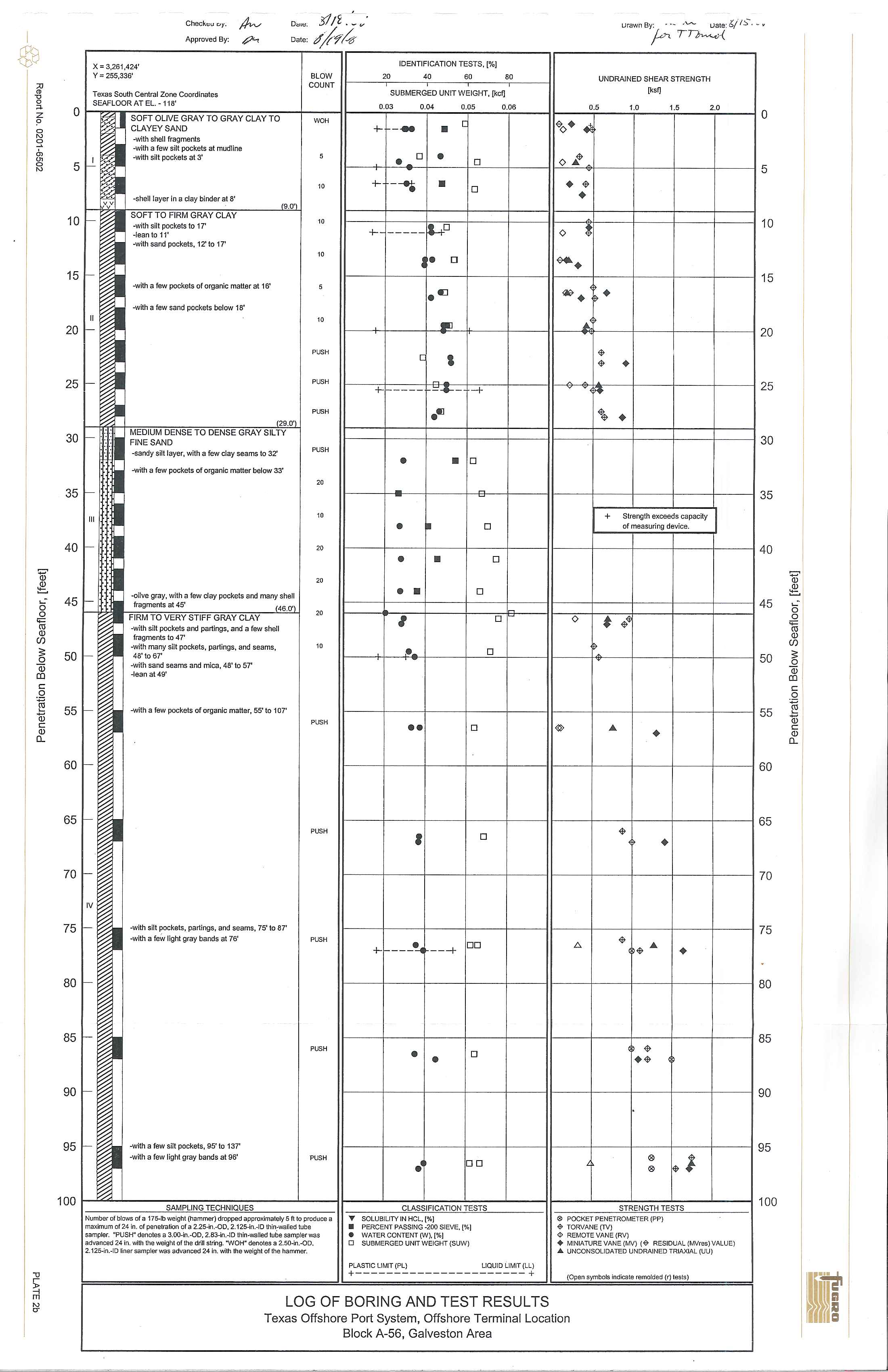
x
=
3
,2
61,424
'
ID
EN
T
IFICATION T
E
STS,
(
%}
Y
=
255,336
'
BLO
W
20
40
60
80
COUN
T
Texa
s
Sou
th
Cen
t
ra
l
Zone
Coo
rdi
na
t
es
S
U
BMERG
ED
UNIT
WEIGH
T,
[kcIJ
SEAF
L
OOR AT
EL.
- 11
8'
0
.
03
0
.
04
0
.
05
0
.
08
D
~W
SOFT
O
L
N
E
GRAY
TO GRAY CLAY
TO
WOH
[
C
LA
YEY SAND
+-
-
•
-with shell
fragments
S
~
I
-with a
few
silt pockets
at mudline
-with sil
l
pockets
al
3'
5
•
0
•
0
1
~
-5h,
,,
lay"
'0
"
'
ay
b'od,,,'8'
10
+-
-~
•
0
vv
t-
19
.0
'
-
31-
SOFT TO
F
I
RM
GRAY CLAY
-
with silt
pockets to
17'
10
-lean to 11'
+-
-
----
Il+O
-
-with
sand
pockets, 12'
to
17'
10
I •
0
S
f--
-
-
w
ith a few pockets of o
rg
anic
matter
at
16
'
5
.
~
15
-
-
w
ith
a
few sand
pockets
be
l
ow
18'
"
10
-
2D
)
I-
-
P
US
H
[
,
5
1-
•
PUSH
+-
=
+C
--+
25
•
PUSH
.~
12
9.0'
)
-
::
MEDIUM DENSE
TO DENSE
GRAY SILTY
3D
FINE
SAND
..
-sandy silt
l
ayer, with
a few
clay seams
t
o
32'
PUSH
..
•
•
0
-with a
f
ew
pockets of organic matter below 33'
20
35
j-
III
10
•
~
0
4D
)
-
20
•
•
0
20
-
oilve
gra
y, with
a few clay pockets
and
many
shell
•
•
0
5
1-
fragments
a
t
45'
(46
.
0')
t-
20
F
I
RM
TO
VERY
S
TIFF
GRAY
CLAY
I
0
-with
silt pockets and
partings, and a few shell
-
f
ragments to
47'
-
with many silt pockets
,
partings, and seams,
10
•
0
-
48' to 67
'
45
50
-
w
ith sand seams and
mica,
48
'
to
57'
-lean at
49'
55
.1-
.-w
ith
a
few
pockets of
organic matte
r
,
55'\0
1
07
'
P
US
H
••
0
6D
)1-
65
i-
PUSH
,
0
7D
I-
I
V
I-
-
.with
s
i
lt
pockets, pa
rt
ings,
and
seams,
75'
to
87'
-
w
i
th a
f
eW
li
ght g
r
ay bands at 76'
P
US
H
f-----II!.
DO
+-
---+
75
80
II-
I
I-
-
PUSH
•
0
•
85
'
r-
90
%
~
;
r-I_
.
wlth a
few
silt
pockets, 95'
to 1
37
'
~
-with a
few
l
ight
gray
band
s
at
96'
PUS
H
•
DO
~
I
t::a
SAMPLING
TECHNIQUES
CLASS
IFI
CAT
I
ON
TESTS
95
100
Number
o
f
bl
o
ws of a
17
5
.Jb
w
ei
ght (hammer) dr
o
pped approx
i
mately 5 flto produce a
.,.
SOLUB
ILI
TY
IN H
C
L,
[
%]
maxim
u
m o
f
2
4 in
. o
f pene
t
ration of a 2
.
25
-
in.
-
OO
,
2
.
125-I
n.-10 thin.•wa
ll
ed
lube
•
PER
C
ENT
PASSING
.200 S
I
EVE
.
[',I,]
samp
ler
. "PUSH
"
denote
s
a 3
.
oo
-
ln
.-
00, 2.83-
l
n..10
thin.walled
tube
sa
m
ple
r
was
•
WATER CONTENT
(W),
[
%
]
advanced
2
4
i
n
.
'NIlh
th
e
weight of \h
e
drill siring
.
'WOH" de
noles
a
2
.
5O-In
.
-OO.
0
SU
B
M
E
RGED
UNIT WEIGHT (SUW)
2.125.in..10
l
i
n
er
s
a
mp
le
r wa
s
advanced 24 In. wi
th the
weight of
the
hammer.
PlASTIC
LI
MIT (
P
I..)
LIQUID
UMI
T
(
LL
)
+
----------------------
+
LOG OF BOR
IN
G AND TEST RESULTS
ura
w
n B
y
:
.
__.v-..
uale:
6
/
1
::;'-
,
fnT~
UNDRAINED
S
HE
AR S
T
RENG
TH
(
ksl]
0
.5
1
.
0
1.
5
2
.
0
~<>
••
<>~
•
~
•
<>
~
-.
~
.
~.
•
~
~
•
~
~
•
+
S
tr
eng
t
h exceeds ca
p
acity
of
measuring
d
e
vi
ce
.
<>
t
;~
~
@
...
•
~
•
~
.t;.
~
...
•
~
.~
II
~I
II
S
T
RENG
TH
T
ES
TS
o
POC
KET PEN
ET
ROM
ET
ER (PP)
$
T
Q
RVANE
(TV)
<I>
REMO
TE
VANE (RV)
•
M
INI
A
TURE
VANE (MV)
(~
RES
ID
UAL (MVres)
VALU
E
}
.6
UN
C
ON
S
O
LI
DA
T
ED UNDRAINED TR
I
AX
I
A
L
(UU)
(
Ope
n
sym
b
o
l
s i
n
dica
t
e
remolded (r)
l
ests)
T
exas
Offshore Port S
y
stem,
Offshore
Terminal L
ocation
Block A-56
,
Galveston Area
o
5
10
15
20
25
3D
35
40
='
tV
~
45
~
-
0
0
<=
I1l
tV
(fJ
5
0
:;:
.Q
tV
co
c
.
Q
55
ro
~
c
tV
[L
60
65
7D
75
8D
85
9D
95
1DO
...
)
f..
•
I
1
~
I
~
~
I
-J
b
.
o~
O<;~
~,,~
~
~
c
0
~
<'
t-~
:.:.
ji-
i
~
I.
~
~
"
<
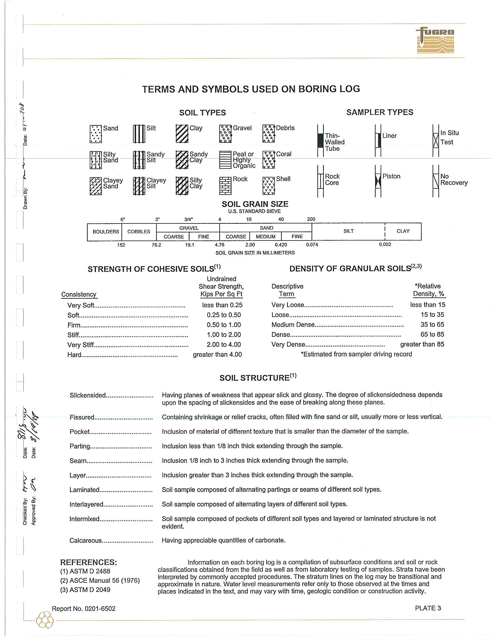
TERMS AND SYMBOLS USED ON BORING LOG
SOIL TYPES
SAMPLER TYPES
DSand
m
Siit
~C
l
ay
~GraVel
~Oebris
••
••
~Thin-
~Lin
er
~In
Situ
...
• •
..
Walled
T
est
Tube
m
Silly
m
SandY
~Sand
Y
~pe
ato
r
9.9.. Coral
• Sand
. Slit
'. Clay
Highly
..
•
Organic
••
~Pi
stan
~Clayey
m
C
lay
ey
m
Silly
I
Rack
~Shell
~RaCk
~Na
Sand
Si
lt
Clay
"
Core
Recovery
"
"
SOIL GRAIN SIZE
u.s. STANDARD SIEVE
31"
"
4
10
40
200
GRAVEL
SAND
SILT
CLAY
COARSE
FINE
COARSE
MEDIUM
FINE
152
76.2
19.1
4.76
2.00
0.420
0.074
0
.
002
SOi
l
GRAIN
SIZE IN
MILLIMETERS
STRENGTH OF COHESIVE SOILS(I)
Undrained
DENSITY OF GRANULAR SOILS
2,3)
Consistency
Very Saft..................................................
Saft............................................................
Shear Strength.
Kips
Per
S9
Ft
Des
criptive
Term
Very
L
oose
....................
:
............................
Loose
.........,
....................................................
.Relative
Density.
%
l
ess
than
15
15
ta
35
Firm
...... " ...................................................
less
than 0.25
0.25
ta
0.50
0.50
ta
1.00
1.00
ta
2.00
2.00
ta
4.00
Medium Dense
....... ,......
...................................
35 to 65
Stiff
............................................................
D
ense
.............................................................
65
to
85
Very Stiff
....................................................
Very Dense.............................
,..............
greater
than
65
Hard
..................................................... greater
than
4.00
.Eslimated
from
sampler driving record
SOIL STRUCTURE
(I)
Slickensided
.... "',.,',.." ......
,,.,
Having planes of weakness that
appea
r
slick
and glossy. The degree
o
f
slickensidedness depends
upon
the spacing
of
s
l
ickensides and
th
e ease
of breaking along these
p
lanes.
Fissured
....." ...
",..,.", .......
,.,..
Containing shrinkage or relief
cracks,
otten filled with fine
sand
or sill, usually
more
or
less vertica
l
.
P
ockeL...............................
Inclusion
of
materia
l
of different texture that Is
s
m
aller
than
the diameter of
th
e sa
mp
le.
Parting..................................
InclUsion less
than
1
/6
inch thick extending
through t
he
sample.
Seam..........
..........................
Inclusion
1
/8
inch
to 3 Inches thick extending through the sample.
Layer......
..............................
I
nclusion
greater
than
3 inches thick extending
through the
sample.
Laminated................
"""..
,,...
Soil sample
composed
of alternating partings or seams of
different
soil
types
.
lnterlayered
.. "."...................
.
Soil sample composed
of altematlng
layers
of different soil types.
Intermi
xed
.............................
Soil sample composed
of pockets of different
soil
types and
layered
or laminated
structure Is
not
ev
ident.
Calcareous
...... ,.....................
REFERENCES:
(1)
AS
TM
D
2488
(2)
ASCE
Manual
56
(1976)
(3)
AS
TM
D
2049
Having appreciable quantities
of carbo
nate
.
I
nformation
on each boring
l
og
is
a
com
pilation of
subsurface conditions and
so
il
or rock
classifications
obtained from the field
as well as
from laboratory testing
o
f
samp
l
es. Strata
have
been
interpreted by commonly
accepted
procedures. The
stratum
lines on the
log
may be transitional and
approxi
mate in
nature.
Water level measurements
r
efer
only
to
those observed
at
the times and
places
indicated
in
the text,
and
may
vary with
time, geologic
condition or construction act
i
vity.
I
Repart Na.
0201-6502
-
@
------
PLATE
3
I
~
'-
1
%
I
~
~
I
~
~
1
°
-J
,
~~
~~
"'"'~
I
8
-
8
-
I
~
(
1
~ ~
~
o
,
~
.
~
u
~
«
~
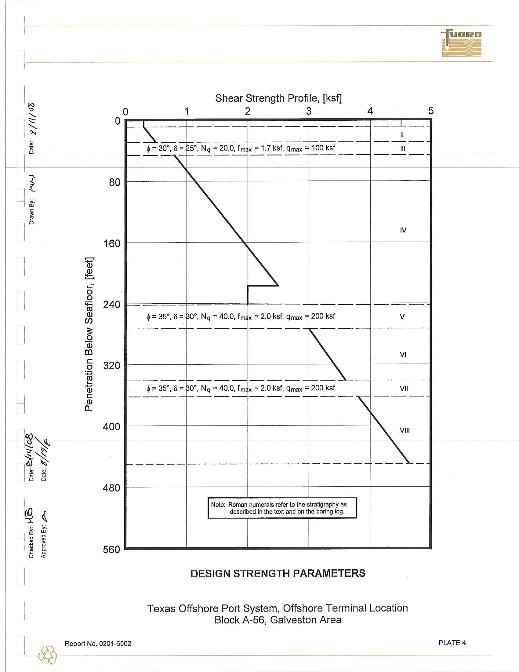
Shear Strength Profile, [ksf]
o
o
1
2
3
r-s=,-
'
-
f-
---
4
5
-
.
---1...-
1
'af
~
...:
o
80
160
'iii
240
Q)
(1)
o
~
W
al
c
.Q
320
~
.§
Q)
C
a..
Q)
400
480
560
--_.-
--_.-
II
~
~
~
=30
.
,
Ii:-
1----
--_.-
--_.-
------
5
.
, N
q
=
20.0, 1m
x
=1
.
7 ksl, qma
x
'
100
ksl
III
--
~
------
--_.-
f---.-
------
'\
r\.
IV
""
~
=
3
5
.
, B=
0., N
q
=40
.
0, 1m
x
=2
.
0 ksl, qm
ax
'
200 ksl
V
--_.-
r----
--_.-
~-
.
-
------
VI
--_.-
----
--_
.
-
r---~-
------
$ =35
.
,
B=
0
.,
N
q
=40.0
,
1m
x
=2
.
0 ksl, qma
x
'
200 ksl
V
II
--_.-
----
--_.-
r---\
------
r'\.
f------
------
------
------
-~-
I
Note: Roman num
e
rals refer to th
e
SlratigraPhl~
described
i
n
the text and
o
n the b
o
ring log
.
.
_--- ----
DESIGN STRENGTH PARAMETERS
Texas Offshore Port System,
Offshore
Terminal Location
Block A
-
56, Galveston
Area
I_
@
Report N
o.
0
2
01
,
6502
PLATE 4
I
~
~~-
I
~
'-
I
~
.2!
•
1
0
j'
I
:
~
~
1
0
"'"
Q)
~
..:
0
0
t;::
nl
Q)
If)
:::
0
Q)
OJ
c
0
:;::;
-
....
nl
Q)
-1
c
Q)
a...
I
~~
~~
I
" "
iii
1;j
o
0
ill
"i
~
l
:ti :ti
~
•
~
•
>
~
~
~
n
o
«
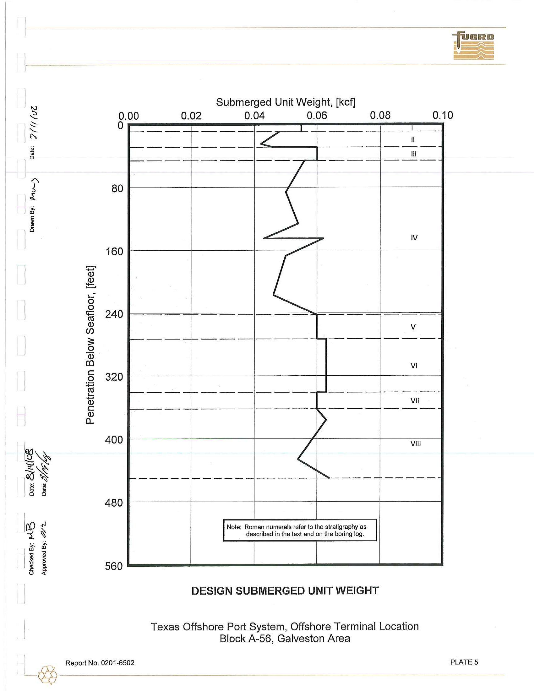
Submerged Unit Weight, [kcf]
o
0
.
00
0.02
0.04
0
.
06
0.08
0
.
10
_-L
80
160
240
320
400
480
560
-
.-
-
.
-
~
-
-
/
I!
--_.-
---
---------
III
---
.
-
--------
---
----
--
-
/
j
IV
./
V
f-----
1----
-----
--_.-
------
VI
f-----
1-
---
--_.-
t---.-
------
VI!
f-----
1-
---
---.-
~.--.-
------
(
VIII
~
~~~
~-
-
~~-~~
~~~~~-
~~~-~-
-----
Back to top
IN
ole:
R
oman
numerals
r
efe
r
to
the
s
tr
atig
raphy
as
I
described in the
text
and
on
the
boring
fo
g
.
DESIGN SUBMERGED
UNIT WEIGHT
Texas
Offshore
Port System,
Offshore
Terminal
Location
Block A
-
56
,
Galveston
Area
1__
@
Report
No
.
0201-6502
P
LA
TE
5
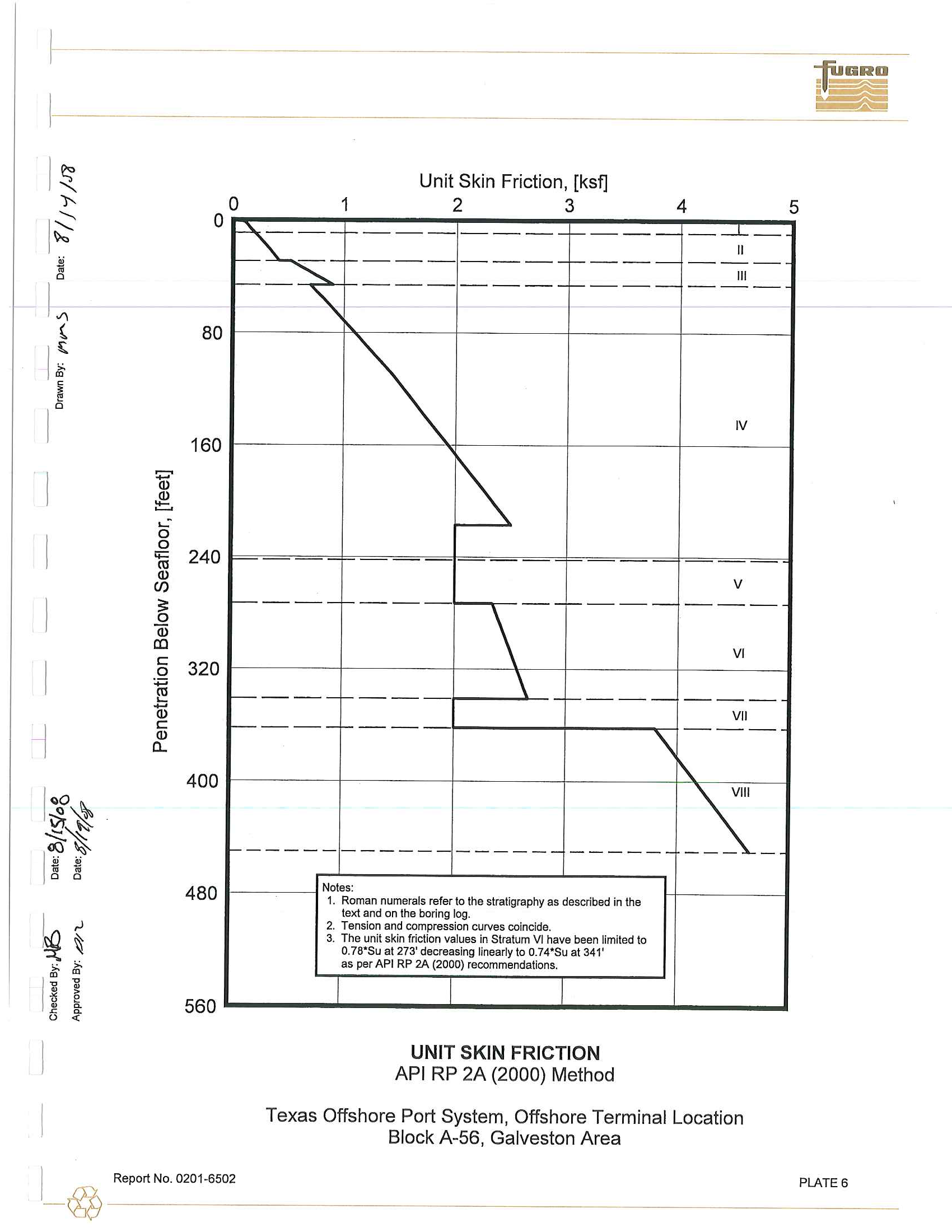
Unit Skin Friction, [ksf]
o
o
1
2
3
4
80
160
240
320
400
480
560
~
-
1----
---
.
-
f--
---
-
--
'-
------,-
f--
--
-
--
"
------
---,-f-----
""
1----,-
---
\
-
--_
.
-
1----,-
r
--
\
.
-
---,-
1----
'
-
r
--
\
------
------
--
-
-
-
-
------
N
oles
:
1
.
R
oma
n nu
merals
r
e
f
er to
th
e s
t
rat
i
gra
p
hy as
de
scri
b
ed
i
n t
he
text
a
nd o
n t
he borin
g l
o
g
.
2
.
T
ensio
n and
comp
r
ess
i
o
n
curv
e
s co
i
nc
i
de
.
3
.
T
he
u
ni
t s
k
i
n f
ri
c
ti
o
n
val
ues in
S
t
ratum V
I
h
ave been
l
i
mi
t
e
d t
o
0.
78*Su
a
t
27
3
' dec
r
e
a
si
ng
li
nea
rl
y t
o
0
.
7
4*
Su
at
3
41
'
as
pe
r A
PI R
P 2A (2000)
re
commen
dat
ions.
UNIT SKIN FRICTION
API
RP
2A (2000) Method
_
,
--1-_
II
------
III
------
I
V
V
------
VI
--_.
-
V
II
--
-
---
\.
-~-
Texas Offshore Port System, Offshor
e
Terminal Location
Block A-56, Galveston Area
I
R
epo
rt N
o
.
020
1
.6
5
02
-~
-------------------------
5
P
LA
TE
6
is'
::::c
I
~
*
1
0
"'I
~
-
I
~
ili
~
I
~
"'"
<ll
~
~-
0
0
t;::
ro
en
<ll
:::
0
<ll
[l)
C
0
:;:;
ro
~
-
<ll
l
c
<ll
a..
l
%l~
'!~
I
~
"j
11i
lG
o
0
I
~ ~
1
~ ~
u
~
•
u
•
>
.
u
e
~
~
~
u
-<
Unit
End
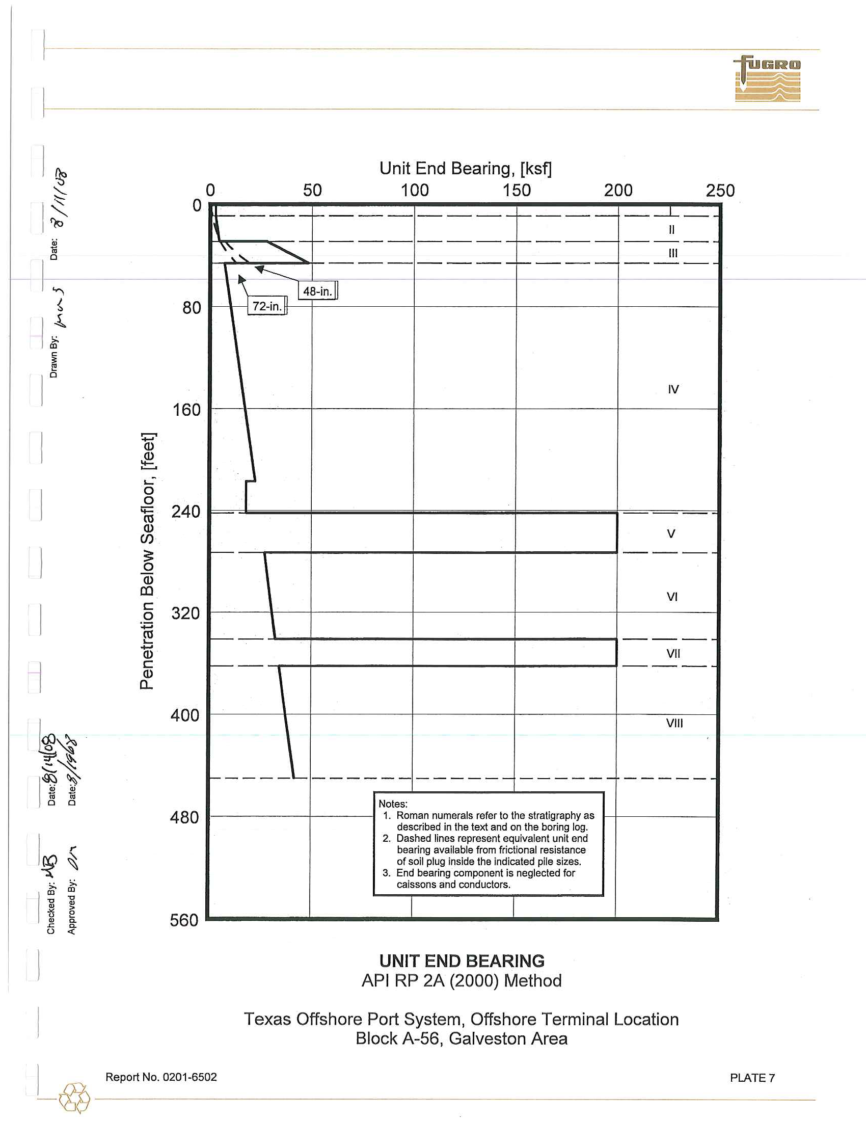
Bearing, [ksf]
o
o
50
100
150
200
250
1----
_.-.1..._
80
160
240
320
400
480
560
r------
----
--_.-
~'."
"",,-
----
--_.-
f----
----
--_.-
1----
--
----
-1
72-in
.
li~
--
r
'--
--
--
1- ____'-
------
------
------
Notes:
1.
Roman
numerals refer to the stratig
r
aphy as
described in
the
text
and on
the boring
log.
2.
Dashed lines
represent equivalent
unit
end
bearing availab
l
e
from
frict
i
onal
resistance
of soil plug inside the ind
i
cated pile sizes.
3.
End bearing
component
is
neglected
for
caissons and conductors.
---
UNIT
END BEARING
API RP
2A
(2000) Method
II
------
III
------
IV
V
----
VI
----
VII
----
VIII
-----
Texas Offshore Port System, Offshore Terminal Location
Block A
-
56, Galveston Area
1
___
~
__
R
_
e
_
p
_
o
_
rt
_
N
_
O
_
.
_
02
_
0
_
1
_
-6
_
5
_
0
_
2
____________________________________________________________________
P
_
LA
__
T
_
E
_
7
____
_
l
I
~
.
~
I
~
I
~
~
I
~
~
1
0
~~
-;r~
......
~
1
010
*
_
'"
1;j
o
0
I
~ ~
I
~
~
u
u
~
g,!
.
o
e
~
~
~
L) «
Ultimate Axial Capacity, [kips]
o
o
3000
6000
9000
12000
15000
_......L __
16
:l!S
.....
o
-
80
160
'lii
240
w
CJ)
Qi
~
£Il
5
320
~
w
c
w
Il..
400
480
560
r-------
1----
-----
r-
--
-
-
II
~---
1-
---
-----
1-----
-------
III
-------
-----
r----
-------
-
-
~
~
~
~
'\
\
IV
'\
,
~
\
~---
V
f----
\
r---~y\
r-----
------
"
~
VI
----
1----
-'~
--------
\
p---
VII
-----
-
---
--~
---
-
-
~
VIII
~
"-
~----
1------
------
------
------
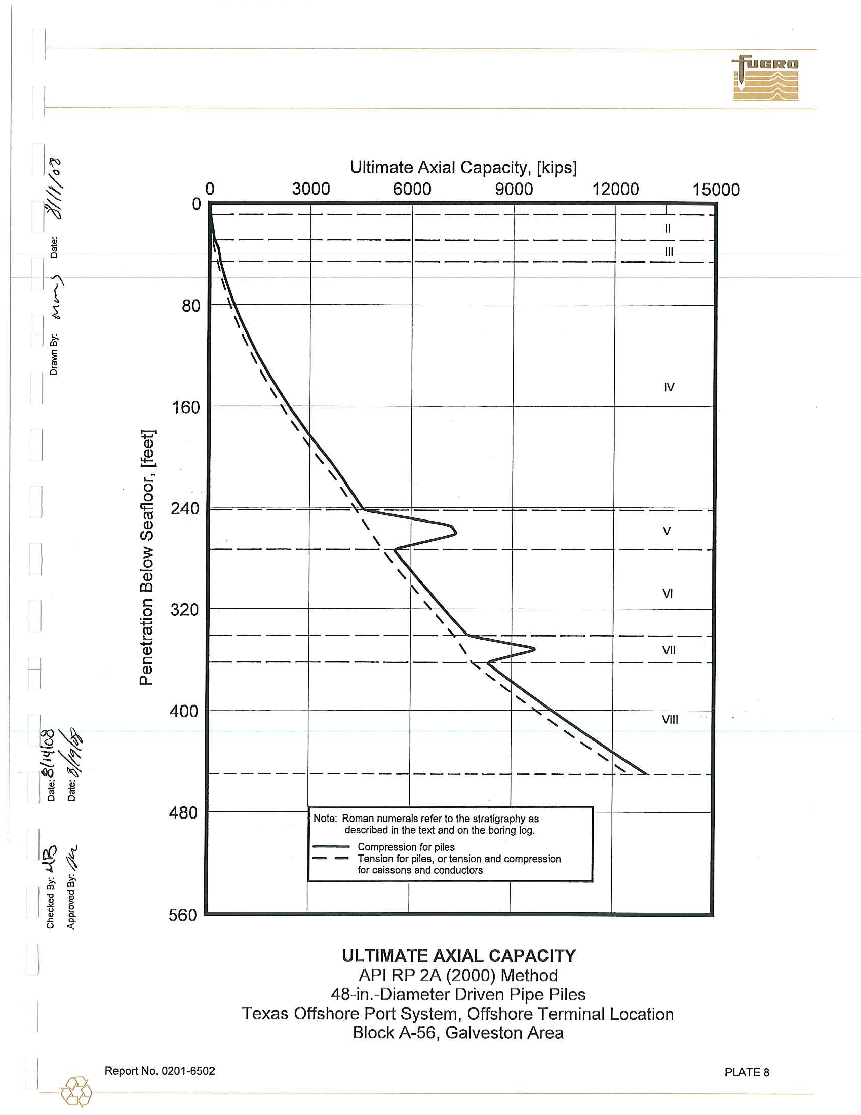
Note: Roman numerals
refer
to
th
e st
ratigraphy
as
described
in the
text
and
o
n
the
boring log.
--
Compression for piles
-
-
Tension for piles,
or tension
and
compression
for
caissons and conductors
ULTIMATE AXIAL
CAPAC
ITY
API RP
2A
(2000) M
et
hod
48
-
in.
-D
iamet
e
r
Driven Pipe Piles
Texas Offshore Port System, Offshore Terminal Location
Block
A
-56
,
Galveston Area
1___
~
_
R
_
e
_
po
_
rt
__
N
_
o
_
.o
_
2
_
o
_
1
_
-6
_
5
_
o2
______________________________________________
____
__________________
P
_
LA
__
T
_
E
_
B
____
___
I
1
~
I
"
~
•
I
o
~
~
I
t
§
~
1
0
I
I
l
I
~~
~~
!
i<XJ~
•
fti
ii
o
0
~~
..
~
I
~ ~
~
.
•
>
jj
.
e
~
~
~
o
"
"'"
Q)
~
..:
0
0
c;::
CIl
Q)
en
~
.2
Q)
al
c
0
:;:;
-
....
CIl
Q)
c
a..
Q)
o
o
80
160
240
320
400
480
560
Ultimate Axial Capacity, [kips)
5000
10000
15000
20000
25000
----
----
----
----
----
-----
------------ ----
------------
----
----
-------- ----
\
_L
----
\
\
,
----
------
--
----
-----
-----
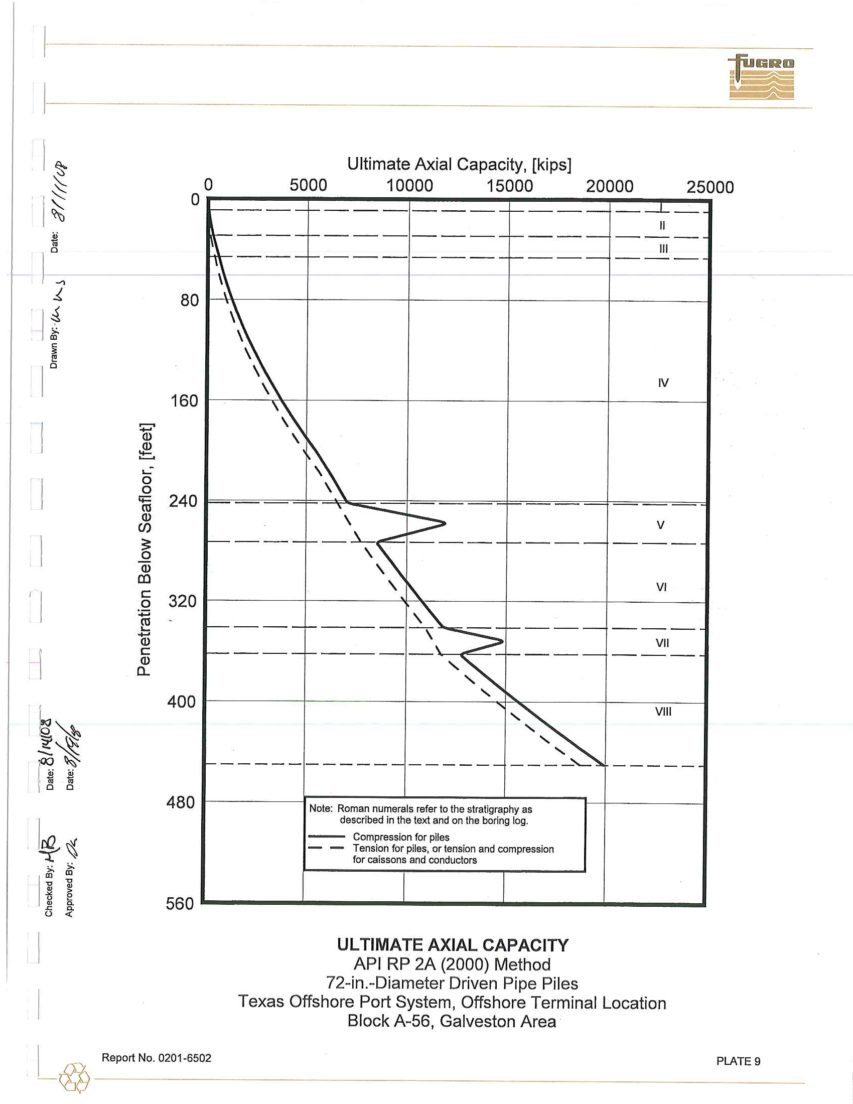
Note
:
Roman numerals refer to
the stratigraphy
as
described
in the
text
and
on the
boring
log
.
Compression for piles
Ten
sio
n
for
piles,
or tension
and compression
for caissons
and conductors
ULTIMATE AXIAL CAPACITY
API RP 2A (2000)
Method
72-
in
.-
Diameter Driven Pipe Piles
II
-------
III
------
-
IV
------
V
------
VI
------
VII
------
VIII
-----
Texas Offshore Port System, Offshore Terminal Location
Block A-56, Galveston Area
1
__
~_
_
R
e
_
p
_
o
_
rt
_
N
_
o
_
.
_
o
2
_
o
_
1
_
-6
_
5
_
o2
________________________________
P
_
LA
_
TE
_
9
____
I
~
'--
I
J::-
~
I
I
~
I
I
~
I
~
l
bo
~~
V1
,,~
.::::..~
I
~
fi
o
0
1\0
~
>.
~
1
;;; '::
ii •
t5
.
e
~
~
~
"
"'
PENETRATION
BELOW
CURVE POINTS
MUDLINE
(feel)
1
2
3
4
5
0
.
0
I
0.00
0.00
0
.
00
0
.
00
0.00
z
0.00
0
.
08
0
.
15
0.27
0.38
1
.
0
I
0.00
0.03
0
.
05
0
.
07
0.09
z
0.00
0.08
0.15
0.27
0.38
6.0
I
0.00
0.05
0
.
08
0.12
0.14
z
0.00
0.08
0.15
0.27
0.38
9.0
I
0.00
0.06
0.10
0.14
0.17
z
0.00
0.08
0.15
0.27
0
.38
29.0
I
0.00
0.13
0
.
21
0.31
0
.38
z
0.00
0.08
0.15
0.27
0.38
29.
0
I
0.00
0.52
0.52
z
0.00
0.10
48
.
00
46.0
I
0.00
0
.
90
0.90
z
0.00
0.10
48.00
46.0
I
0.00
0
.2
1
0
.
35
0
.
52
0.62
z
0
.0
0
0.08
0
.
15
0
.
27
0.38
1
09.
0
I
0
.
00
0.43
0
.
71
1.07
1.28
z
0.00
0.08
0
.
15
0.27
0
.
38
217.0
I
0.00
0.75
1.25
1.87
2.25
z
0.00
0.08
0.15
0.27
0.38
217.0
I
0.00
0.60
1.00
1.50
1.80
z
0.00
0.08
0.15
0.27
0.38
242.0
I
0.00
0.60
1.00
1.50
1.80
z
0.00
0.08
0.15
0.27
0.38
242.0
I
0.00
2.00
2.00
z
0.00
0
.10
48.00
273.0
I
0
.
00
2.00
2.00
z
0
.
00
0.10
48.00
273
.
0
I
0.00
0.70
1
.
17
1.76
2.11
z
0.00
0.08
0.15
0
.
27
0
.3
8
341
.
0
I
0
.
00
0.80
1
.3
3
2
.
00
2.40
z
0.00
0.08
0.15
0
.
27
0.38
341.0
I
0.00
2
.
00
2.00
z
0.00
0.10
48
.
00
362.0
I
0.00
2
.
00
2.00
z
0.00
0.10
48
.
00
362.0
I
0.00
1
.
14
1.90
2.85
3.42
z
0.00
0.08
0.15
0.27
0.38
450.0
I
0.00
1.39
2.32
3.49
4.18
z
0
.
00
0.08
0.15
0.27
0.38
Notes: 1.
"t" is
mobilized
soil-pi
le
adhesion,
[ksf]
.
2.
liZ"
is axial pile displacement, [in.].
3.
Data for tension and compression
coi
n
cide.
AXIAL LOAD TRANSFER DATA
(T-Z DATA)
API
RP
2A
(2000) Method
48-in.-Diameter Driven Pipe Piles
6
7
8
0.00
0.00
0
.
00
0.48
0.96
48
.
00
0.10
0.09
0
.
09
0.48
0.96
48
.
00
0.16
0.14
0
.14
0.48
0.96
48.00
0.19
0.17
0.17
0.48
0.96
48.00
0.42
0.38
0
.
38
0.48
0.96
48.00
0.69
0.62
0
.
62
0.48
0
.
96
48.00
1.43
1.28
1
.
28
0.48
0
.
96
48
.0
0
2.50
2.25
2.25
0.48
0.96
48
.
00
2.00
1
.
80
1
.
80
0.48
0.96
48.00
I
2.00
1.80
1.80
0.48
0.96
48.00
2.34
2
.
34
2
.
34
0.48
0
.
96
48
.
00
2
.
66
2
.6
6
2
.
66
0
.
48
0
.9
6
48
.
00
3.80
3.42
3.42
0.48
0.96
48
.
00
4.65
4.18
4.18
0.48
0.96
48.00
Texas Offshore Port System,
Offshore
Terminal Location
Block
A
-56,
Galveston Area
I
__
~__
Re
_
po
_
rt
_
N
_
O.
_
02
_
0
_
1-
_
65
_
02
__________________________________________________
P
_
~
_
T
_
E
_
lo
_
a
_
1--
~
I
~
"",
~
~
"
l
I
:
<D
I
!
1
-1
I
I
~~
~~
I
"
~ ~
"
I
~ ~
~ ~
'E
-g
jj
.
e
~
~
~
u
«
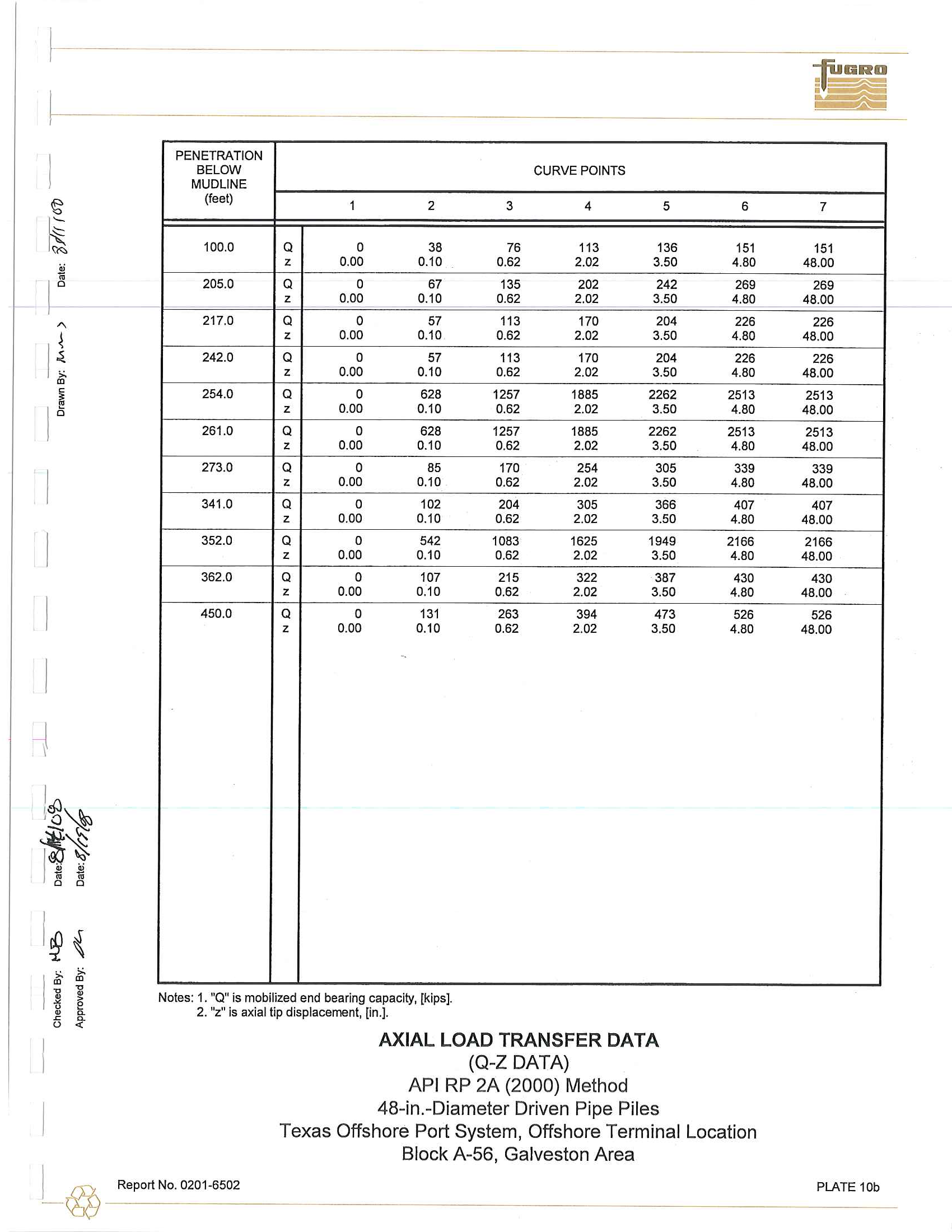
PENETRATION
BELOW
CURVE
POINTS
MUDLINE
(feel)
1
2
3
4
5
100
.
0
Q
0
38
76
113
136
z
0
.
00
0
.
10
0
.
62
2
.
02
3
.
50
205
.
0
Q
0
67
135
202
242
z
0
.
00
0
.
10
0
.
62
2.02
3.50
217.0
Q
0
57
113
170
204
z
0.00
0
.
10
0
.
62
2.02
3.50
242
.
0
Q
0
57
113
170
204
z
0.00
0.10
0.62
2.02
3.50
254
.
0
Q
0
628
1257
1885
2262
z
0
.
00
0
.
10
0
.
62
2
.
02
3.50
261
.
0
Q
0
628
1257
1885
2262
z
0
.
00
0
.
10
0
.
62
2
.
02
3.50
273
.
0
Q
0
85
170
254
305
z
0.00
0
.
10
0
.
62
2
.
02
3.50
341
.
0
Q
0
102
204
305
366
z
0
.0
0
0
.
10
0
.
62
2
.
0
2
3
.
50
352
.
0
Q
0
542
1083
16
25
1949
z
0
.
00
0.10
0
.
62
2
.
02
3
.
50
362
.
0
Q
0
107
215
322
387
z
0.00
0.10
0
.
62
2
.
02
3.50
450.0
Q
0
131
263
394
473
z
0
.
00
0
.
10
0.62
2
.
02
3
.
50
Not
e
s
:
1.
"0"
is mobilized end bear
i
ng capacity,
[kips]
.
2
.
"z"
is a
x
ial
tip
displacement,
[in
.
]
.
AXIAL LOAD TRANSFER DATA
(O
-Z
DATA)
API
RP
2A
(2000) Method
48
-
in.
-
Diameter Driven Pipe Piles
6
151
4
.
80
269
4.80
226
4.80
226
4
.
80
2513
4.80
2513
4
.
80
339
4
.
80
407
4
.
80
2166
4
.
80
430
4
.
80
526
4.80
Texas Offshore Port System,
Offshore
Terminal Location
Block
A
-5
6,
Galveston
Area
_I_
@
Report No
.
0201-6502
7
151
48
.
00
269
48
.
00
226
48
.
00
226
48
.
00
2513
48
.
00
2513
48
.
00
339
48
.
00
407
48
.
00
2166
48
.
00
430
48
.
00
526
48.00
PLATE
lOb
l
~
"-
I
§
~
l'
!
~
!
!
\
I
1
'
~
Ift'{
~,,~
)
1.)
~
~
!i
" !l
~
~
I
u
~ ~
u
• •
r
~
e
~
~
u
~
-
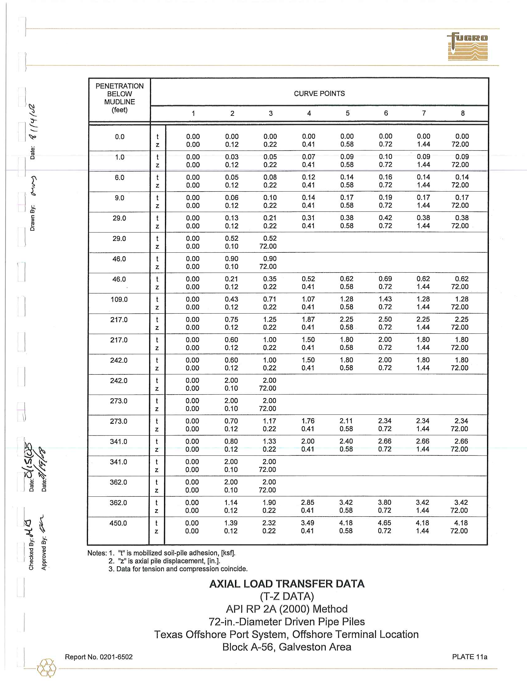
PENETRATION
BELOW
CURVE POINTS
MUDLINE
(feet)
1
2
3
4
5
0.0
t
0.00
0.00
0
.
00
0.00
0.00
z
0
.
00
0.12
0.22
0.41
0.58
1.0
t
0
.
00
0
.
03
0
.
05
om
0
.
09
z
0.00
0.12
0.22
0.41
0.58
6.0
t
0.00
0.05
0.08
0
.
12
0.14
z
0.00
0
.
12
0
.
22
0.41
0.58
9
.
0
t
0.00
0
.
06
0.10
0.14
0.17
z
0.00
0
.1
2
0.22
0
.
41
0
.
58
29
.
0
t
0.00
0
.1
3
0.21
0.31
0.38
z
0
.
00
0.12
0.22
0.41
0.58
29
.
0
t
0.00
0
.
52
0.52
z
0
.
00
0.10
72.00
46.0
t
0
.
00
0.90
0.90
z
0.00
0.10
72.00
46.0
t
0.00
0.21
0
.
35
0
.
52
0.62
z
0
.
00
0.12
0.22
0.41
0.58
109.0
t
0.00
0.43
0
.
71
1
.
07
1.28
z
0.00
0.12
0.22
0.41
0.58
217.0
t
0.00
0.75
1.25
1.87
2.25
z
0.00
0.12
0.22
0.41
0.58
217.0
t
0.00
0
.
60
1.00
1.50
1.80
z
0.00
0.12
0.22
0.41
0.58
242.0
t
0
.
00
0.60
1.00
1
.
50
1.80
z
0.00
0.12
0.22
0.41
0.58
242.0
t
0
.
00
2.00
2
.
00
z
0.00
0
.
10
72.00
273.0
t
0.00
2
.
00
2
.
00
z
0.00
0.10
72.00
273.0
t
0.00
0.70
1.17
1.76
2.11
z
0.00
0
.
12
0.22
0.41
0.58
341
.
0
t
0
.
00
0.80
1
.
33
2.00
2.40
z
0.00
0
.
12
0
.
22
0.41
0
.
58
341.0
t
0.00
2.00
2.00
z
0
.
00
0.10
72.00
362.0
t
0
.
00
2.00
2
.
00
z
0.00
0.10
72
.
00
362.0
t
0.00
1
.
14
1.90
2
.
85
3.42
z
0
.
00
0.12
0.22
0.41
0.58
450.0
t
0.00
1.39
2.32
3.49
4.18
z
0.00
0.12
0.22
0.41
0.58
Notes: 1.
"
t
"
is
mobilized
soil.pile adhesion, [ksf].
2.
"
z
"
is axial pile
displacement
,
[in
.
].
3. Data for tension and compression coincide.
AXIAL LOAD TRANSFER DATA
(T
-Z
DATA)
API
RP 2A (2000) Method
72
-
in.
-
Diameter Driven Pipe Piles
6
7
0.00
0
.
00
0.72
1.44
0.10
0
.
09
0.72
1.44
0.16
0.14
0
.
72
1.44
0.19
0.17
0.72
1.44
0.42
0
.
38
0.72
1.44
0
.
69
0.62
0.72
1.44
1.43
1.28
0
.
72
1.44
2
.
50
2.25
0.72
1.44
2.00
1.80
0.72
1.44
2.00
1.80
0
.
72
1.44
2.34
2
.
34
0.72
1.44
2.66
2.66
0.72
1.44
3
.
80
3.42
0
.
72
1.44
4.65
4.18
0.72
1.44
Texas Offshore Port System, Offshore Terminal Location
8
0.00
72.00
0.09
72.00
0
.
14
72.00
0.17
72
.
00
0.38
72
.
00
0
.
62
72.00
1.28
72.00
2.25
72.00
1.80
72
.
00
1
.
80
72.00
2.34
72
.
00
2
.
66
72.00
3.42
72.00
4
.
18
72.00
I
Block A-56, Galveston Area
_
@
Report No
.
0
2
01.6502
PLATE 11a
l
.
~
'--
1
~
I
~
~
I
I
:
I
!
l
I
~t
1
~~1
"
"
'"
b
~
..
l
:t
-g
<l>
-g
~
.
e
~
u
~
<{
~
PEN ETRATION
BELOW
CURVE
POINTS
MUDLINE
(feet)
1
2
3
4
5
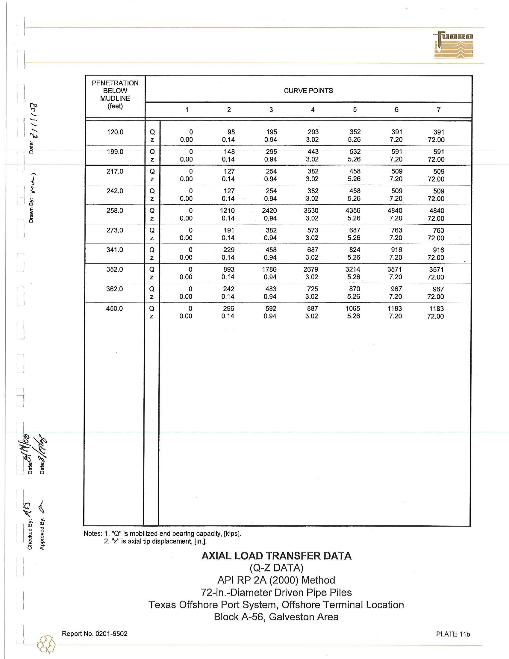
120.0
Q
0
98
195
293
352
z
0.00
0.14
0.94
3.02
5.26
199.0
Q
0
148
295
443
532
z
0.00
0.14
0.94
3
.
02
5.26
217
.
0
Q
0
127
254
382
458
z
0.00
0
.
14
0.94
3.02
5.26
242.0
Q
0
127
254
382
458
z
0.00
0.14
0.94
3
.
02
5
.
26
258.0
Q
0
1210
2420
3630
4356
z
0
.
00
0
.
14
0.94
3
.
02
5
.
26
273
.
0
Q
0
191
382
573
687
z
0
.
00
0
.
14
0.94
3.02
5.26
341
.
0
Q
0
229
458
687
824
z
0.00
0.14
0.94
3.02
5.26
352.0
Q
0
893
1786
2679
3214
z
0.00
0.14
0.94
3.02
5.26
362.0
Q
0
242
483
725
870
z
0.00
0.14
0.94
3.02
5.26
450.0
Q
0
296
592
887
1065
z
0.00
0.14
0.94
3.02
5.26
Notes:
1. "Q"
is
mobilized end bearing capacity,
[kips].
2
.
liZ"
is axial
tip
disp
l
acement
,
[in.].
AXIAL LOAD TRANSFER DATA
(O
-
Z
DATA)
API
RP 2A (2000) M
e
thod
72
-
in.
-
Diameter Driven Pipe Piles
6
391
7.20
591
7.20
509
7
.
20
509
7.20
4840
7.20
763
7.20
916
7
.
20
3571
7
.
20
967
7.20
1183
7.20
Texas Offshore Port System, Offshore Terminal Location
Block A-56, Galveston Area
7
391
72
.
00
591
72.00
509
72.00
509
72.00
4840
72.00
763
72.00
916
72.00
3571
72.00
967
72
.
00
1183
72.00
~_
@
Report
No.
0201
-
6502
PLATE llb
1
1
~
.:;;;
I
~
-
~
..
I
!
'"
I
l
I
1~
~~
.
~
'
8 d
I
~~
~
m
i
I
u
it
I
1-
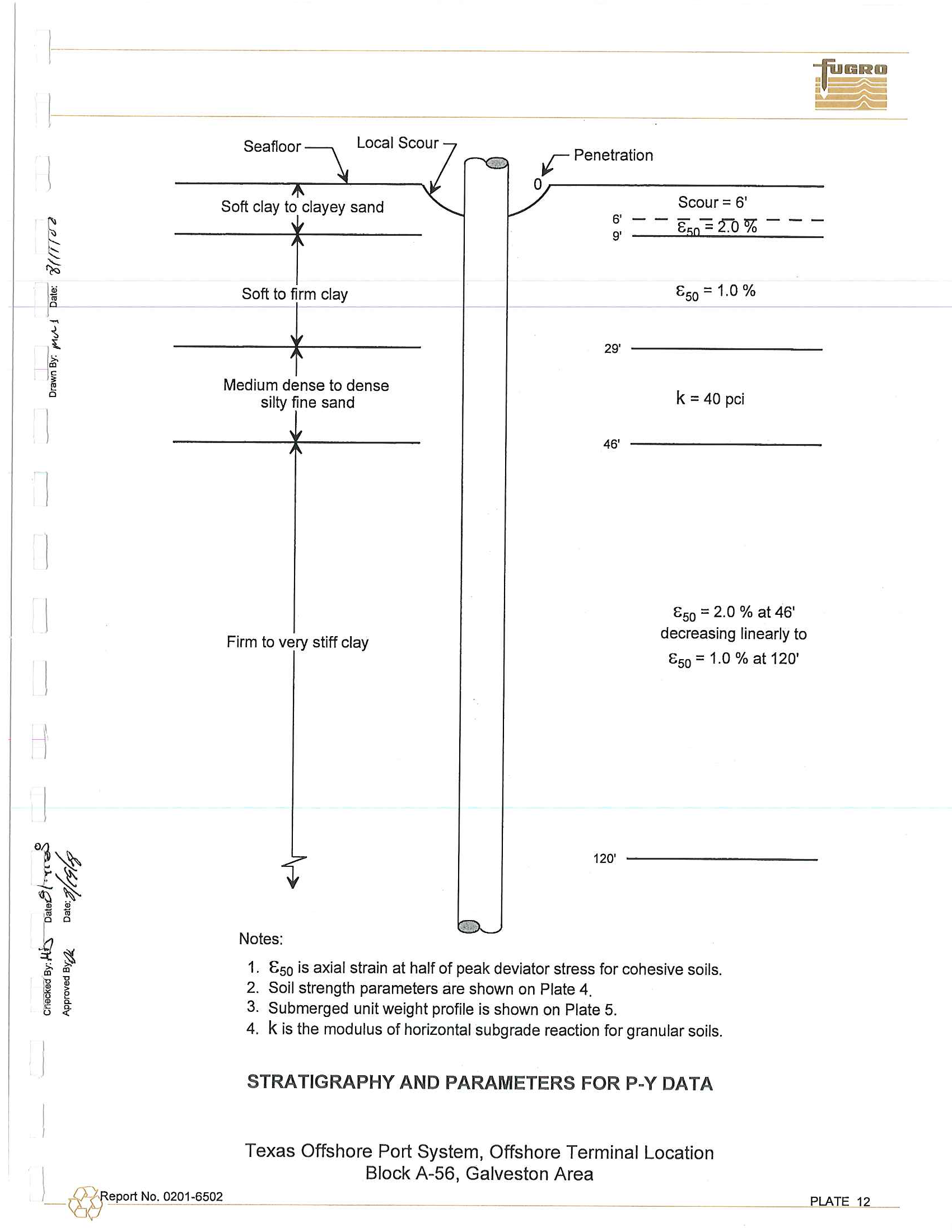
Seafloor
Local
Scour
r
Penetration
0r------------------
Scour
=
6'
Soft 0',
Y"'"
,",d
6'
9'
- - -
E5
0
-="""0""
L
-
--
.
~
70
1>50=1.0%
Soft to
rd.'
29'
Medium
dense to dense
silty fine sand
k=40pci
eport N
o.
0201-6502
Firm to very stiff clay
Notes:
46'
120'
1>50 = 2
.
0
%
at 46'
decreasing linearly to
1>50
=
1.0
%
at
120'
1.
E50
is axial strain at half of peak deviator stress for cohesive soils.
2. Soil strength parameters are shown on Plate 4
.
3. Submerged unit weight profile is shown on Plate 5
.
4
.
k is
the
modulus
of horizontal
subgrade
reaction for granular soils
.
S
TRATIGRAPHY
AND PARAMETERS FOR P-Y DATA
Texas Offshore Port System, Offshore Terminal Location
Block
A-56, Galveston Area
PlATE 12
l
~
*
1
'-.
I
'"
~
I
"
t
1
I
~
\
!
1
l
l
~~
'!!~
I
~
iii
~
.!!
o
il
1
0,0
N
"t~
I
~ ~
~
•
~
•
>
~
~
u
~
«
~
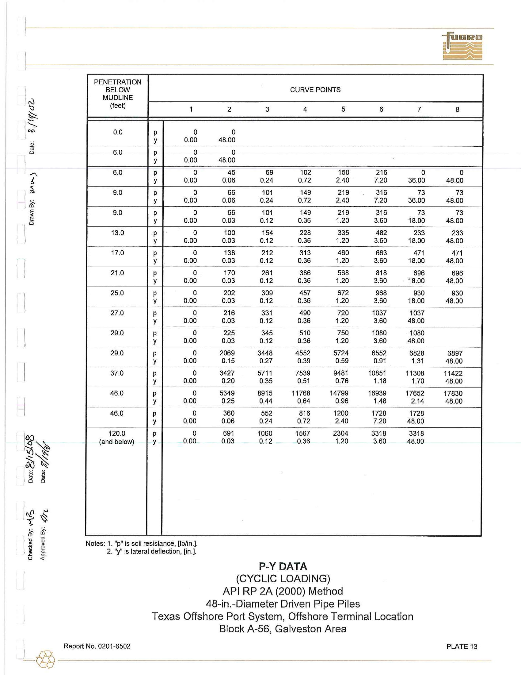
PENETRATION
BELOW
MUDLINE
(feet)
1
0.0
P
0
y
0.00
6
.
0
P
0
y
0.00
6.0
P
0
y
0
.
00
9
.
0
P
0
Y
0.00
9.0
P
0
Y
0.00
13
.
0
P
0
Y
0.00
17.0
P
0
Y
0.00
21.0
P
0
Y
0
.
00
25
.
0
P
0
Y
0.00
27.0
P
0
Y
0.00
29.0
P
0
Y
0
.
00
29.0
P
0
Y
0
.
00
37.0
P
0
Y
0
.
00
46
.
0
P
0
Y
0
.
00
46.0
P
0
Y
0.00
120
.
0
P
0
(and
below)
Y
0.00
Notes
:
1
.
lip"
is
soil
resistance
,
[Ib/in
.
].
2. '''I' is
lateral deflection, [in.].
CURVE
POINTS
2
3
4
5
0
48.00
0
48.00
45
69
102
150
0.06
0.24
0.72
2.40
66
101
149
219
0.06
0.24
0.72
2.40
66
101
149
219
0.03
0.12
0.36
1.20
100
154
228
335
0
.
03
0.12
0.36
1.20
138
212
313
460
0.03
0.12
0.36
1.20
170
261
386
568
0
.
03
0
.
12
0.36
1
.
20
202
309
457
672
0.03
0
.
12
0.36
1.20
216
331
490
720
0.03
0.12
0
.
36
1.20
225
345
510
750
0
.
03
0.12
0.36
1.20
2069
3448
4552
5724
0.15
0.27
0.39
0.59
3427
5711
7539
9481
0.20
0.35
0
.
51
0.76
5349
8915
11768
14799
0.25
0.44
0.64
0.96
360
552
816
1200
0
.
06
0.24
0.72
2.40
691
1060
1567
2304
0.03
0.12
0.36
1
.
20
-
--
-
.
-
--
--
P-Y DATA
(CYCLIC
LOADING)
API
RP 2A
(2000)
Method
48
-
in.
-
Diameter Driven Pipe Piles
6
7
216
0
7
.
20
36.00
316
73
7.20
36.00
316
73
3.60
18.00
482
233
3.60
18.00
663
471
3
.
60
18.00
818
696
3.60
18
.
00
968
930
3.60
18
.
00
1037
1037
3
.
60
48.00
1080
1080
3
.
60
48.00
6552
6828
0.91
1.31
10851
11308
1.18
1.70
16939
17652
1.48
2
.
14
1728
1728
7
.
20
48
.
00
3318
3318
3.60
48
.
00
Texas Offshore Port System, Offshore Terminal Location
Block
A-56,
Galveston Area
_I
_
@
Rep
o
rt No
.
0201-6502
8
0
48.00
73
48
.
00
73
48.00
233
48.00
471
48
.
00
696
48.00
930
48.00
6897
48.00
11422
48.00
17830
48.00
PLATE
13
~-
I
~
I
~
I
~
'"
!
I
~
m
~
\
0
l
~~
I
..
"
.!!
iii
1':
0
I
~~
I
u
~ ~
jj
•
u
•
~
. -
~
~
L)
~
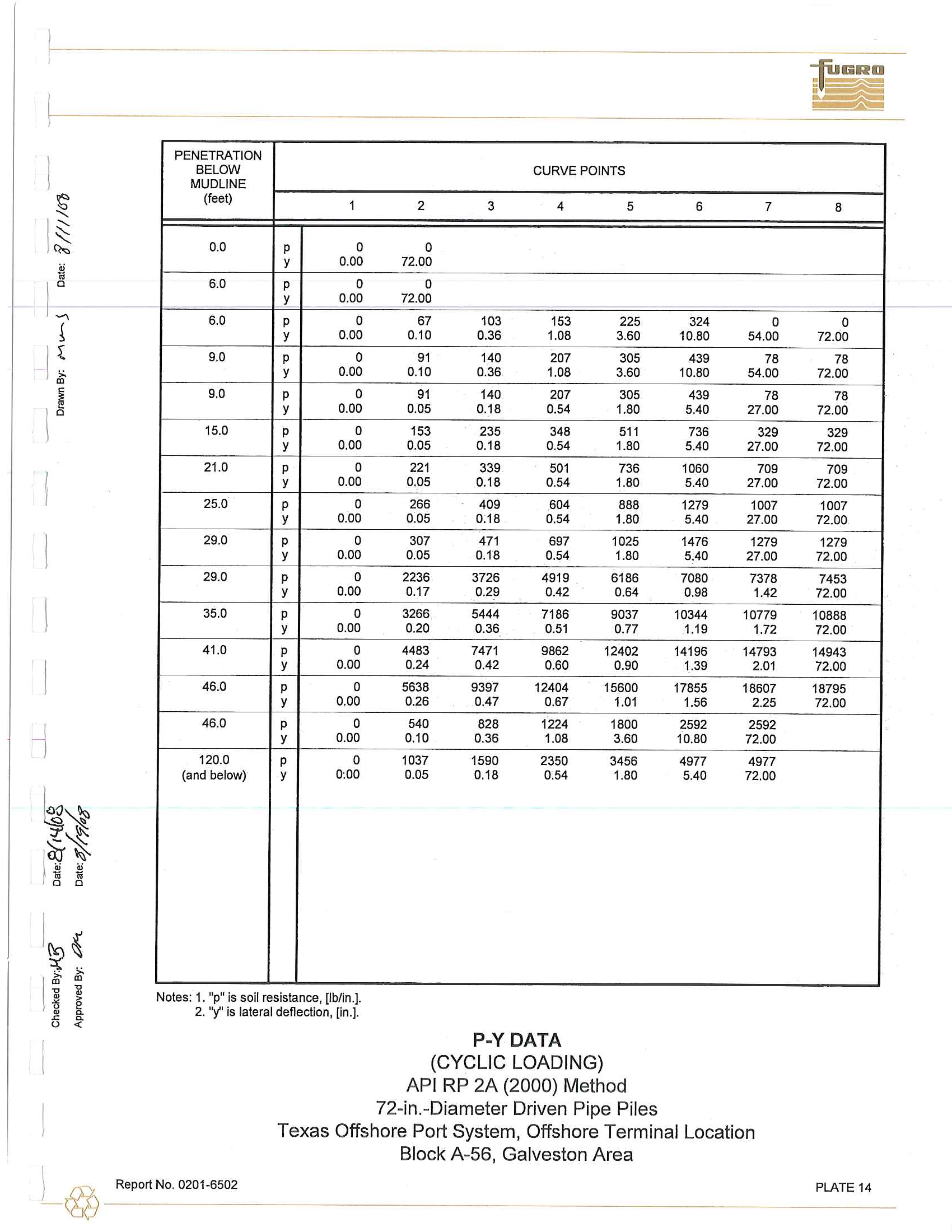
P
E
N
E
T
RA
TI
ON
BE
L
OW
MUDUNE
(feet)
1
0.0
P
0
y
0
.
00
6.0
P
0
y
0
.
00
6
.
0
P
0
y
0.00
9
.
0
P
0
Y
0
.
00
9.0
P
0
Y
0
.
00
1
5.0
P
0
Y
0
.
00
21.0
P
0
Y
0
.
00
25
.
0
P
0
Y
0.00
29
.
0
P
0
Y
0
.
00
29
.
0
P
0
Y
0
.
00
35.0
P
0
Y
0
.
00
41.0
P
0
Y
0
.
00
46
.
0
P
0
Y
0
.
00
46
.
0
P
0
Y
0
.
00
120.0
P
0
(and below)
y
0
:
00
Notes
:
1
.
"p"
i
s soil res
i
stance
,
(lb
/
in
.
].
2
.
''y'' is late
r
a
l
deflection
,
[
in.]
.
C
U
RVE POIN
T
S
2
3
4
5
0
72.00
0
72.00
67
103
153
225
0.
1
0
0
.
36
1.08
3.60
91
140
207
305
0.
1
0
0.36
1
.
08
3.60
91
140
207
305
0
.
05
0.18
0.54
1
.
80
153
235
348
5
11
0
.
05
0
.
18
0
.
54
1
.
80
221
339
50
1
736
0.05
0
.
18
0
.
54
1.80
266
409
604
888
0.05
0.
1
8
0
.
54
1
.80
307
471
697
1025
0
.
05
0
.
18
0.54
1.80
2236
3726
49
1
9
6186
0
.
17
0
.
29
0.42
0
.
64
3266
5444
7186
9037
0
.
20
0
.
36
0
.
5
1
0.77
4483
7471
9862
1
2402
0.24
0.42
0.60
0.90
5638
9397
12404
15600
0
.
26
0.47
0
.
67
1
.
01
540
828
1224
1800
0
.
10
0
.
36
1.08
3
.
60
1037
1590
2350
3456
0.05
0.18
0.54
1
.
80
P-Y DATA
(C
Y
CLIC LOAD
IN
G)
AP
I
RP 2A (2000) Method
72-in.-D
i
ameter Dr
iv
en P
i
pe P
il
es
6
7
324
0
10.80
54
.
00
439
78
10.80
54.00
439
78
5.40
27
.
00
736
329
5.40
27
.
00
1060
709
5.40
27.00
1
279
1007
5.40
27.00
1476
1279
5.40
27
.
00
7080
7378
0
.
98
1
.42
10344
10779
1
.
19
1
.
72
1
4
1
96
14793
1..39
2
.
0
1
17855
1
8607
1.56
2
.
25
2592
2592
10
.
80
72
.
00
4977
4977
5.40
72.00
Texas Offs
h
ore Port System, Offs
h
o
r
e Termi
n
a
l
Loca
ti
on
B
l
ock A-56, Ga
l
veston Area
@
Report No
.
0201-
_
65
_
0
_
2
__
_
8
0
72
.
00
78
72
.
00
78
72.00
329
72.00
709
72.00
1007
72.00
1
279
72.00
7453
72.00
10888
72.00
14943
72.00
1
8795
72
.
00
PLATE 14
1
-
@
;0
ro
"
,.
o
Z
o
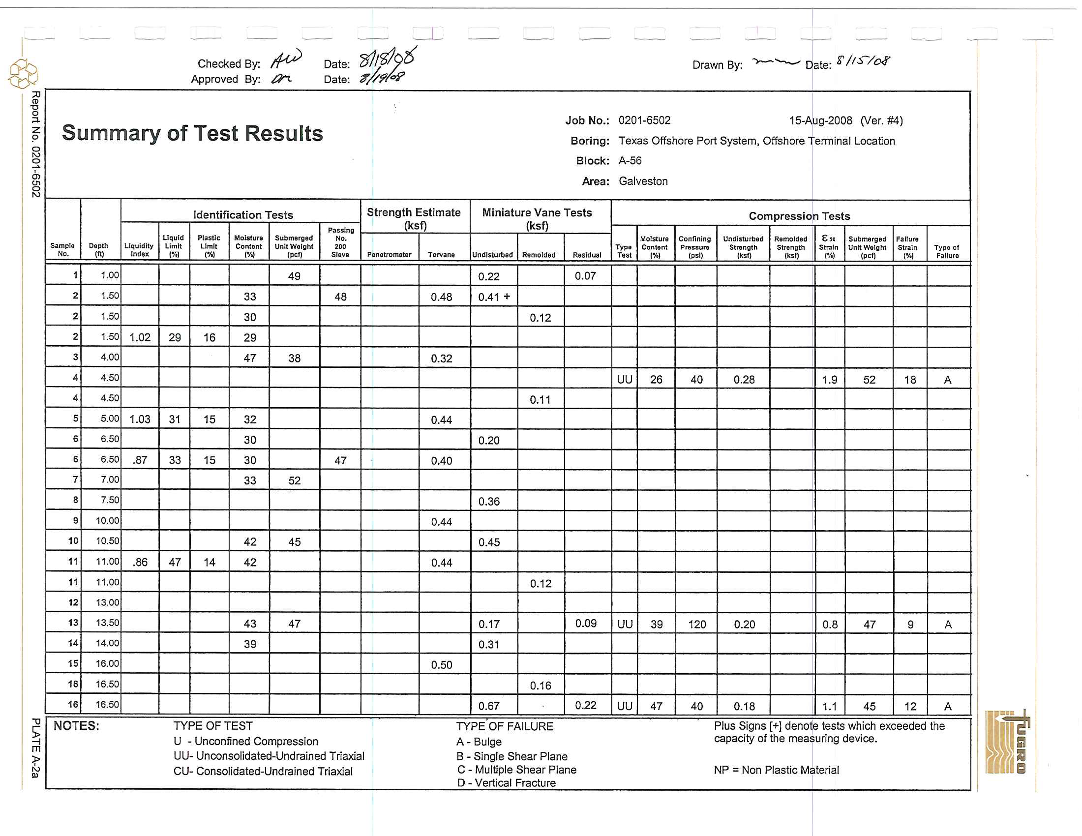
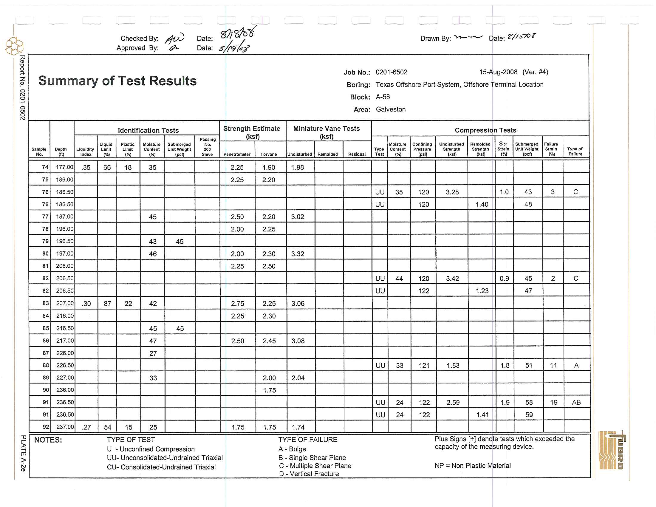
Summary
of
Te
s
t
Results
2
01
in
'"
2
"
~
m
w
~
5.:Impl,
"'o~
No.
,ft,
1
1.00
2
1.50
2
1.50
2
1.50
3
4.00
4
4.50
4
4
.
50
5
5
.00
6
6.50
6
6
.
50
7
7
.00
8
7.50
9
10
.0
0
10
10.50
11
11.00
11
11.00
12
13
.0
0
13
13.50
1.
14.00
15
16
.00
16
16
.
50
16
16.50
NOTE
S:
Liquidity
Ino..
1.02
1.03
.87
.86
Identification
Tests
Pass
i
ng
Uquld
PIntle;
Molstura
Submerged
No.
Umlt
Umlt
Conllnl
U
nltWlll111t
,V<
,V<
""
'"
(pel)
Sl,vI
49
33
48
30
29
16
29
47
38
31
15
32
30
33
1
5
30
47
33
52
42
45
47
14
42
43
47
39
TYPE
O
F TE
S
T
U
- Unconfined Compression
UU-
Unconsolidated-Undra
ine
d
T
r
i
axial
CU- Consolidated
-
Undrained
Tria
xial
---L
--
--
--
Job
No.:
Boring:
Blo
ck:
Ar
ea:
Strength Estimate
Miniature
Van
e
Tests
(ksf)
(ksf)
Penetrometer
T
orvant
Undisturbed
Remolded
R.sJdual
0.22
0.07
0.48
0
.
41
+
0.12
0
.
32
0.11
0.44
0
.2
0
0.40
0.36
0.44
0.45
0.44
0.12
0.17
0
.
09
0.31
0.50
0
.
16
0.67
0.22
TYPE
O
F F
A
ILU
RE
A
-
Bulge
B
- Single Shear Plane
C
-
Multiple Shear Plane
0- Vertical
Fracture
-- --
--
--
-
--
-
-
Drawn By:
-------- Dat
e:
go
/rS-/o.r
T
0201
.
6502
15.Aug
-2008
(Ve,.
#4)
T
exas Offshore
Port System, Offshore Te
r
minal
L
ocation
A
-
56
Galveston
Comp
r
ession
Tests
Mo!$tur.
Connn
t
n"
Undisturbed
Rlmol"-d
•
•
Submervl
d
Falfurl
Typ
e
ConMnt
Pressure
SIAlngth.
Sl
l1In
gth
SIr"
I
"
Unit Welllht
St
r
a
in
T
YPlo
l
Tnt
""
[psi)
'''.
'''.
1
%)
(pel')
l't
.,
Fallur.
UU
26
40
0.28
1.9
52
18
A
UU
39
120
0.20
0.8
47
9
A
UU
47
40
0
.
1
8
1.1
45
12
A
If
Plus
Signs
[
+]
denote t
ests
whic
h
e
x
ceeded the
capacity of the
measuring d
ev
i
ce.
NP =
Non Plastic Material
1
-
~
"
o
'"
Z
o
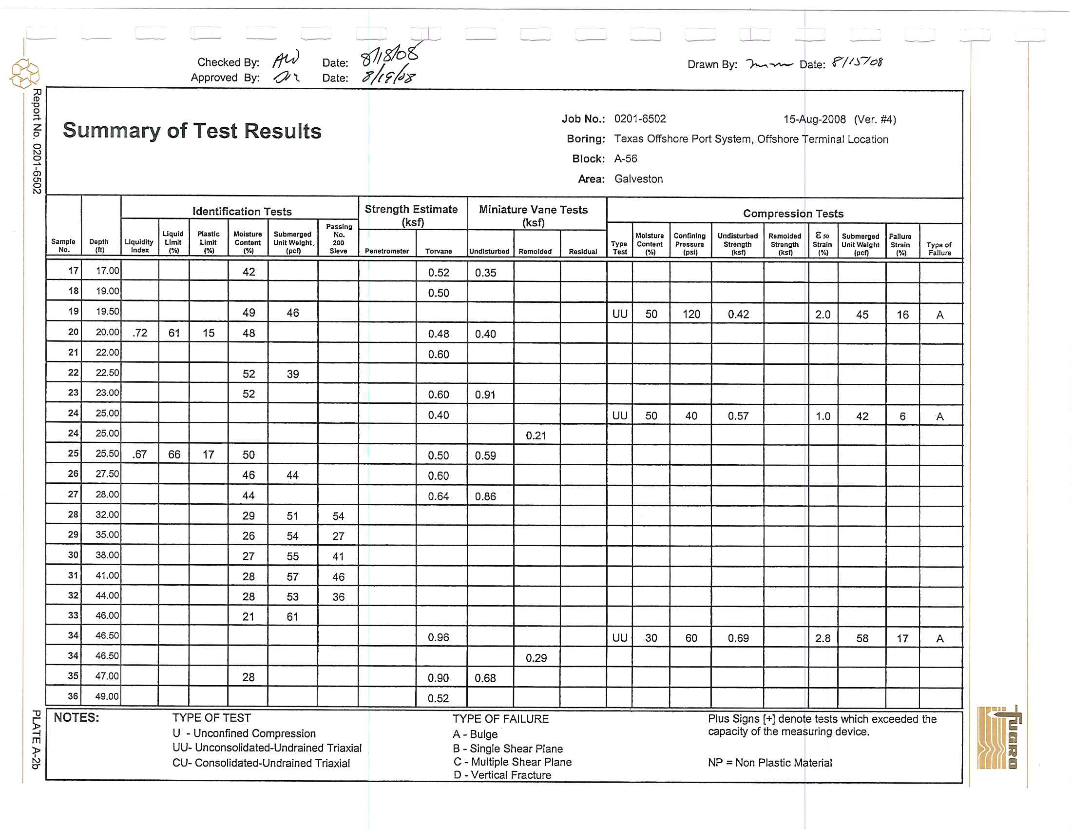
Summary
o
f
Test Res
ult
s
2
~
in
gJ
'"
""0
m
~
tT
~
Sampl.
O,pth
No.
")
17
17
.00
18
19
.0
0
1.
'9
.
50
20
20.00
2
1
22
.0
0
22
22.50
23
23.00
24
25.0
0
24
25
.
00
2
5
25.50
2
6
27
.
50
27
28.00
28
32.00
2.
35
.00
3
0
38
.
00
31
41.00
3
2
44.00
33
46.00
3
4
46
.
5
0
34
46.50
35
47
.00
36
49.00
N
O
T
ES
:
Uquld
i
ty
Indu;
.
7
2
.67
I
d
e
n
t
ification
Tes
t
s
Pnslng
Uquld
Pla.tlc
Molstur.
Submergld
No
.
L
lmll
LImit
Cont
,
n
t
U
nltW,lgh
t
,
,.,
'"
,%)
)%)
)pot)
S~y.
42
4
9
4
6
61
1
5
48
5
2
39
52
66
17
50
46
44
4
4
2
9
5
1
54
26
54
27
2
7
55
41
2
8
57
46
28
53
36
2
1
6
1
2
8
TYPE
OF
TE
S
T
U
-
U
n
co
n
fine
d
Co
m
pression
UU- Unco
n
soli
d
ated-
U
ndrained
T
riaxial
CU
-
Co
n
so
li
da
t
e
d-Un
dra
i
ned
T
riaxia
l
t
-
--
-- --
Job No
.:
Bor
i
ng:
B
lo
c
k
:
Ar
ea
:
Stre
n
g
t
h Es
t
im
ate
Miniatu
r
e V
a
n
e
T
es
ts
(k
s
f)
(
ksf)
P
,nlt
r
ometlr
T
orv..n
.
Urnllsturbt'd
Remold
,
d
R
tsldl,l3l
0.52
0.3
5
0.50
0.
4
8
0
.40
0.60
0.60
0.9
1
0.40
0.21
0.50
0.59
0.60
0.64
0.86
0
.
96
0
.
29
0.90
0.68
0.52
T
Y
PE
O
F
F
A
IL
UR
E
A
- B
ulg
e
B
- Sing
l
e Shea
r
Plane
C
-
M
ul
tip
l
e S
h
ea
r Pl
ane
D
- Ve
rt
ical
Fracture
--
-
--
-
--
-
,
-
-
,-
----,-
D
r
aw
n
By
:
r-..,
~
D
ate:
1?'/1.;708
020
1
-6502
15-Aug
-
2008
(Ver.
#4)
Texas
Offs
ho
re Port System, Offshore Term
i
na
l
Location
A
-
56
G
a
lveston
Compr
ess
i
o
n T
es
t
s
MoI$lurl
ConOn!n"
UmSrsturbad
Rlmold'
d
£,.
Submerged
F
a
llurl
Ty"
Cont
,
nt
P"'
'''
UI'1l
StL'll
n
ljth
Stl'llngth
Stf"llin
UnitW,rght
Strain
TYPI
of
To.
,.,
(psi)
'''''
''""
..
<
)po"
('10)
F
a
Uu
...
U
U
5
0
120
0.42
2.0
4
5
1
6
A
UU
50
40
0.5
7
1
.
0
42
6
A
U
U
3
0
60
0
.6
9
2.8
58
17
A
Pl
us Sig
n
s
[
+] de
n
ote tes
t
s w
hi
c
h e
xceeded the
capac
i
ty of the measuring device.
NP
=
No
n P
las
t
ic
Material
1-
@
'"
ro
"0
o
;+
-
z
o
Summary of Te
s
t
Results
l<l
~
0,
8
-u
~
S~mpl
.
Depth
No.
"I
37
49.50
38
50
.
00
39
56.00
40
56
.
50
40
56.50
40
56.50
41
5
7
.00
42
66
.
00
43
66.50
44
67.00
45
76.00
4
6
76.50
46
76
.
50
47
77.00
4
8
86.00
49
86.50
50
87.00
51
96.00
52
96.50
52
96.50
53
97
.
00
54
106
.
00
NOT
ES
:
Liquid
i
ty
I
ndex
1
.
32
.6
1
Identi
f
ica
t
i
o
n
T
e
s
t~
Liquid
Plastic
MoIsture
S
",
bm,
r
ged
Lim
i
t
L
imit
Con
t
e
nt
Unit
W
eIght
('10)
,%,
('!oj
(pef)
3
2
56
3
1
17
35
33
37
54
3
7
54
17
39
35
52
45
37
TY
PE
O
F TE
ST
U
- U
nco
n
fine
d
Co
mp
ression
.L
-
-- --
-
...
,
J
o
b
N
o
.:
B
ori
n
g
:
B
loc
k:
Ar
ea
:
S
t
re
n
g
th E
s
tim
a
t
e
M
i
niatur
e
Vane Te
st
s
Pissing
(
ksf)
(
ks
f)
No.
'"
Slev.
Penetrometer
T
ON;mlit
Undistu
r
be
d
Remo
l
ded
R
esid
u
a
l
0.58
0
.08
0.1
1
1.
3
0
0.88
1.
00
1
.4
1
0
.
88
1
.
00
1
.
10
1_64
1
.00
1
.20
1
.
50
1.
20
1.
0
8
1.25
1
.75
1
.
25
1.
5
5
1.
72
1.
2
5
1
.50
T
Y
PE
O
F F
A
IL
UR
E
A
-
Bulge
UU
-
Unconsoli
d
a
t
ed-U
n
d
r
ai
n
ed
T
riaxial
B
-
S
ingl
e Sh
e
a
r P
lane
m
n
~
CU
-
Conso
li
dated
-
Und
r
ai
n
e
d Tri
ax
i
a
l
C
-
Mult
i
ple Shear Plane
D
- Vert
i
cal
Fr
ac
t
ure
-
--
~--
--
--
--
--
~
Dra
w
n
B
y:
--,-..
~
D
ate:
Y/M/
0
5'
T
0201
-
6502
1
5
-
Au9
-
2008 (Ve
r
.
#4)
T
exas
Offshore
P
o
rt
Sy
st
e
m,
Offs
h
ore
T
ermi
n
al
L
oca
t
ion
A
-
56
Ga
l
veston
1
Com
p
re
ss
i
on
T
est
s
M
oJstur~
C
o
n
fi
ning
U
n
dl
stu
r
b
,
d
Remo
l
de
d
E,.
S
u
b
me
r
gad
F
illu
••
T
y
p
e
Conten
t
PrtliSurt
Strengt
h
Slnml:llh
Strain
Un
il
W
e
igh
t
S
t
rain
Type
of
T
est
("I
.
)
(ps
i
)
(ksf)
''''"
('!oj
(pef)
('!oj
F
ailure
UU
3
7
82
0
.7
6
2.
2
52
7
A
UU
1
2
1
0
.
33
53
U
U
36
11
8
1.2
7
1
.4
5
1
4
B
UU
121
0.49
53
UU
40
120
1
.75
1
.0
51
6
B
P
lu
s S
i
g
n
s
[+]
de
no
te tes
t
s
w
h
i
c
h
exceede
d
the
ca
p
acity
o
f t
he
measur
in
g dev
i
ce.
NP
= N
on P
l
ast
i
c Ma
t
eria
l
1-
@
~
"8
"
o
z
a,
~
§
-- --
-
---
-
- --
--
Checked By:
1M
Date:
'61/~5
Approved
By:
,t?""
Dat
e:~j7N
Summary of Test Results
--
--
-
Job
No.:
Boring
:
Block
:
Area:
Identification
Tests
Str
en
gth Estimate
Miniature
Van
e
Tests
P~5s1nll
(ksf)
(ksf)
Liqu
I
d
PL3slic
Molstur.
Submlrged
".
S~mpre
O,pth
L1qulcllty
Limit
LImit
Contenl
UnltW,lglII
'"
No.
Iftl
Ind..
(~.)
("/.)
IV.)
(pef)
sr
.....
P,n
l
trom,,!.,
To
rv
.. n.
UndIsturbed
Remold,d
Residual
55
106
.
50
44
44
56
107.00
45
1
.50
1
.75
2
.
04
57
116.00
1
.50
1.50
58
116.50
59
117.00
.
54
48
14
32
1.50
1.50
1.
4
0
6
0
126
.
00
1
.75
1
.
75
61
126.5
0
36
52
6
2
127.00
34
1.75
1
.85
2.49
63
136.00
1.50
1
.75
64
136.50
64
136.50
65
137
.00
46
2.00
1.75
1.64
66
145.30
47
67
14
7.00
NP
21
67
147
.00
25
54
8
68
1
55.50
29
49
87
69
166.00
1.50
1.50
7.
166.50
45
70
166.50
71
167
.00
38
2.00
1.75
2.19
72
176.00
2.00
2.00
73
176
.50
41
46
N
OTES:
TYPE
OF TEST
T
YP
E
OF
FA
I
LU
R
E
U
-
Unconfined Compression
A -
Bulge
UU-
Unconsolidated-Undrained
Tria
x
i
al
8
-
Sing
le
Shear Plane
CU- Consolidated-Undrained
Tri
axial
C
-
Multiple Shear
Plane
0-
Vertical
Fr
actu
r
e
"0
S
m
~
-
- -- --
--
-
-
--
-
---,-
Drawn
By:
~-.....'\..-
Date:
~/("'!>/c:J'l
0201
-
6502
15-Aug-2008
(Ve
r.
#4)
Te
xas
Offshore Port System, Offshore
Terminal
Location
A-56
Galveston
Compre
ssion
Tests
Molstur.
Conllnlng
Undlsturb
,
d
R
,m
o
lde
d
g"
Subm.rg
.d
Failure
Typ,
C
ontent
Pra5Su
"
S
t
reng
t
h
Str.ngth
51",
ln
Unll
W.
lg
ht
Strolln
Type of
Tn
t
1%)
(psI)
I""
(ksfj
1%'
I,of)
(
'h
)
Fallur.
UU
33
1
20
1.22
1
.
6
.
55
7
AB
UU
45
120
1
.94
2.2
46
6
B
UU
122
0.61
45
U
U
29
12
0
1.74
3.3
57
19
AB
UU
35
1
21
1
.58
2.9
45
11
B
UU
123
0.82
50
P
lus Signs
{+] denote
tests
which
exceeded
the
capacity of
the measuring dev
ice.
NP
=
Non
Plastic Material
I
-
@.
"C
o
"-
Z
~
Summary of Test Results
a
N
"
6>
2
"1l
~
m
:;>
N
ro
53mpl..
Depth
No.
{ftl
74
177.00
75
186.00
76
186.50
76
186.50
77
187.00
78
196.00
79
196
.
50
80
197.00
81
206.00
82
206
.
50
82
206
.
50
83
207.00
84
216
.
00
85
2
1
6
.
50
86
217.00
87
226.00
88
226.50
89
227
.
00
90
236.00
91
236.50
91
236
.
50
92
237
.
00
NOTE
S:
Liquidity
lndu
.35
.
30
.27
Ide
n
tifica
tio
n Te
s
ts
P~,sjnlii
LIquid
P
intle
Mo
l
stu
...
Submerged
N,.
LImit
('/0)
L
imit
Conten
t
U
n
it
Weig
ht
".
(%)
{%l
,.'"
Sieve
66
18
35
45
43
45
46
87
22
4
2
45
45
4
7
27
33
54
1
5
25
TYP
E
O
F
TEST
U
-
Unconfi
n
e
d
Compression
u
u-
Unconso
l
idated-Undrained
T
riaxia
l
CU
-
Conso
lid
ated
-U
nd
r
ained
Tr
iaxia
l
-.-L
--
-- --
--
-- --
--
-
--
--
D
r
awn
By
:
........... -
D
a
t
e:
1?11'7'O8'
,
.
-
Jo
b
N
o
.
:
020
1-
6502
1
5-Aug-2008 (Ver.
#4)
B
o
r
i
n
g:
T
exas
O
ffs
h
ore Port System, Offsho
r
e
T
ermina
l L
ocation
B
l
oc
k
:
A-56
Ar
e
a
:
Galveston
I
S
trength
Es
ti
m
ate
M
ini
at
ur
e
V
a
n
e
T
es
ts
C
o
mp
r
es
s
ion T
e
s
t
s
(ks!)
(ks
!)
Moisture
Conflning
Undistu
r
bed
Ramo
l
de
d
E"
S
ub
ml'g'.:!
F
~lIure
Type
Content
Prnsu,e
Streng
t
h
SIren
11th
Str
..l"
Unit Walght
St,aln
T
ypa
of
Penet
r
ometer
T
orvane
Undis
t
urbed
Remo
l
ded
ResIdual
Test
("!o)
(psi)
(ksf)
(ksf)
('!oj
(pet)
(%)
Failure
2.25
1
.90
1
.98
2
.
25
2.20
UU
35
120
3.28
1.0
43
3
C
UU
120
1.40
48
2.50
2.20
3.02
2
.
00
2.25
2.00
2.30
3.32
2
.2
5
2
.
50
UU
4
4
120
3.42
0
.
9
45
2
C
U
U
122
1.23
4
7
2.75
2.25
3
.
06
2.25
2.30
2
.
50
2
.
4
5
3.08
UU
33
121
1
.83
1.
8
51
1
1
A
2.00
2
.
0
4
1.75
UU
24
1
22
2
.
59
1.9
58
1
9
AB
UU
2
4
1
22
1.41
59
1
.7
5
1.75
1.7
4
TYPE O
F F
A
IL
URE
P
lus
Signs [+]
d
eno
t
e
t
es
t
s whic
h
exceeded the
~
1
A
-
Bu
l
ge
capacity of the
m
easuri
n
g dev
i
ce.
B
-
Single Shear Plane
C - Mu
l
tip
l
e Shear P
l
ane
NP
= N
o
n
P
l
as
ti
c Ma
t
e
r
ial
o
-
Ve
rti
cal
Fr
acture
1
-
@
~
"0
o
-
"
o
Z
Summary of Test Results
2
'=
0,
g;
"
-u
S
Silmple
D
epth
No.
1ft,
93
245.50
94
256.50
95
265.50
96
276.00
97
276
.50
97
276
.
50
98
277.00
99
287
.
10
100
290.00
101
297.00
102
305
.
50
102
305.50
103
306.00
104
306.50
105
316.00
106
317.00
107
325.50
108
326.00
108
326.00
108
326.00
109
326
.
50
110
336.00
NOTES
:
Liquidity
I
ndex
.33
.55
.22
Identifi
c
at
io
n
Test
s
Llql,lld
PI~stle
Moisture
Subme
r
ged
LIm
i
t
L
imIt
Conten
t
UnltW.rg
ht
("I.)
('!oj
('!oj
(p
e
t)
23
62
21
54
25
55
80
2
1
41
23
66
25
59
29
11
2
1
56
22
57
44
14
20
TYP
E
O
F TE
S
T
U
-
U
n
confined
Compress
i
on
-L
--
-- --
¥
•
or
-
J
ob No.
:
Bo
rin
g
:
Blo
c
k:
Ar
ea
:
S
t
r
eng
t
h Estimate
Mi
niat
ure
Vane
Te
sts
Passing
(
k
sf)
(k
s
f)
No.
'"
SI.".
P
e
netrometer
Torv
a
na
Undisturbed
R
emo
l
de
d
Res
id
ua
l
1
3
8
4
3
.
50
3.50
3.78
17
23
1.75
76
6.59
3.83 +
T
YPE
O
F F
AILURE
A - Bu
l
ge
UU
-
U
n
conso
l
idated-Undrained T
r
iaxial
m
&
B
-
Sing
l
e S
h
ear
P
l
ane
CU
-
Conso
li
date
d
-Und
r
aine
d Tr
iaxia
l
C
- M
ul
tip
l
e
Shear Plane
o
-
Vertica
l F
racture
--
-- --
--
--
--
-
Drawn
By:
?'-~
Date:
f?11~-/c$'
0201
-
6502
15
-
Au9-2008 (Ver.
#4)
Texas
Offshore
Port System,
Offshore
T
e
r
min
a
l
L
ocation
A-56
Galves
t
on
,
C
ompressi
o
n
T
e
s
ts
Moisl
u
f.
Connn!
n
g
U
n
disturbed
Remolded
E.
S
u
bme
r
ged
Failu
r
e
Type
Conllnl
Pressllre
Streng
t
h
Strength
SI,..!n
Uni
t
Waight
SI",!n
Type
of
T
lSt
('Yo)
(ps
i
)
(
ksf)
,
..
,
('10)
(pel)
('/,)
F
a
lh
.,a
UU
42
123
3.65
0.7
49
2
B
UU
123
1.92
49
UU
23
120
2_22
2_8
55
10
AB
UU
122
0.93
62
UU
12
1
3_82
69
U
U
20
123
4_66
2
.
0
65
10
AB
UU
1
23
3_37
69
Plus Signs [+J denote tests
w
h
ich
exceeded
the
capacity of
the
measur
i
ng
device.
NP
=
Non
Plastic
Materia
l
I
@
;0
rn
"
o
"
o
Z
i3
'"
in
~
~
"
m
;t;
'"
-
-
Summary
of Test Results
Identification
Tests
P
~$$
lng
LIqu
i
d
PI~strc;
Moisture
Submerged
".
S3mpla
O
e
pth
Liquidity
limit
lIm1l
Content
Unit Walght
'"
N,.
1ft)
Index
{'!oj
(%1
('!oj
I,,,,
S
ie
ve
111
336.50
112
337.00
25
113
345.80
23
56
9
115
358
.00
24
57
4
116
366.00
117
366.50
117
366
.50
116
367
.00
.40
55
18
33
1,.
376
.
00
120
376.50
120
376.50
58
121
377.00
25
121
377.00
22
122
386.00
21
51
24
123
396.00
12.
396.50
12.
396
.
50
125
397.00
.38
41
1
5
25
126
406.00
127
406.50
126
407.00
30
12'
416.00
NOTES:
TYP
E
OF T
E
ST
U
-
Unconfined Compression
UU
-
U
n
conso
l
idated-Undrained
T
riaxial
CU
-
Consolidated-Undrained
T
riaxial
----L
..
-
Job No
.
:
Boring:
Block:
Area:
Strength Estimate
Miniature Vane Tests
(ksf)
(ksf)
Pen
e
trometer
Torvana
Undisturbed
Remolded
Residual
3.83 +
4
.
64
3.90
3.66
3.83
+
3
.
75
2.61
2.75
3
.
20
4.00
3.83
+
4.00
TYP
E
OF FAI
L
UR
E
A - Bulge
B
-
Single Shear Plane
C
-
Multiple Shear
Plane
o
-
Vertical
Fr
acture
T
0201-6502
1
5-Aug-2008
(Ver. #4)
Texas
Offshore
Port System, Offshore Terminal
Location
A-56
Galveston
1
Compression Tests
Molst ...r.
Confinlnll
Undisturbed
Remolded
Eo.
Submerged
f~lIur8
Type
Content
Pressure
Strength
Strenllth
Str~ln
UnltWelllht
Strain
Type
of
T.~
{'!oj
(psi)
(ksl)
(ksf)
('/oj
(pef)
('10)
Failure
UU
23
122
3.43
1
.
8
57
11
AC
I
UU
1
22
2.37
55
UU
28
1
21
5.50
1.7
47
4
C
UU
23
120
1.64
I
63
UU
24
120
2.99
2
.
9
60
16
A
UU
26
120
4
.
07
3.2
57
14
AC
UU
122
1.40
61
UU
29
123
4
.
77
2
.
5
49
7
B
Plus Signs
[+]
denote
tests
which exceeded
the
capacity
of
the measuring device.
NP = Non
Plastic
Materia
l
1-
~
ro
"0
,.
o
...
,
z
?
Summary
of
Test
Results
:<3
~
'"
~
S~mpl.
,
•
.
130
131
132
132
133
13.
135
136
137
138
13.
13.
"0
Dtlplh
Uquldlty
Iftl
Index
416.50
417.00
426.00
426.00
426
.
50
427
.00
.31
436
.0
0
436.30
437.00
449
.
00
449.50
449
.
50
450
.
00
Identification
Tests
L
iquid
Pintle
Moisture
Submlrgld
Urn"
Li
mit
Contini
UnltW,rlll'lt
'%1
'%)
1
0
k)
,,,'
32
71
19
35
55
28
62
1
6
24
c//l~"
J
ob No
.
:
Boring:
Block:
Area:
Strengt
h
Estimate
Miniature Vane
Te
s
t
s
Pnslng
(ksf)
(ksf)
S;.eVI
'00
,
•.
PI
.atrOmttlr
Torv~n.
Undisturbed
Rlmoldld
R,sldWlI
3.75
3.83
+
4.39
4.88
3.83
+
3.25
3.76
5
.
12
3.75
3.83
+
0201-6502
15-Aug-2008 (Ver. #4)
Texas Offshore Port System, Offsho
r
e
T
ermina
l
L
ocation
A
-
56
Galveston
Compression
T
ests
Moistur
l
Conllnlng
UndlSWrbld
Remo
l
dld
E.
Submerged
F~lIur.
Typo
Con~nt
Pre$&ur.
Stlllnllih
Strlngth
St~ln
Uolt W,llIht
Stf"illn
TYPlof
T.~
'%)
''''''
''''
''''
1'10)
(pet)
1%
)
F
ailure
UU
30
120
4.67
2.4
48
7
B
UU
121
1.59
54
UU
24
122
5.30
2.4
47
7
B
UU
19
120
1.81
66
UU
21
123
4
.99
1.9
60
8
C
~
NOTES
:
TYPE
OF
TE
S
T
TYPE OF FAILURE
Plus Signs
[+]
denote tests whic
h
exceeded
ttle
--r
U
_
Unconfined Compression
A
_
Bulge
capacIty of
the
measuring
devIce.
~
UU- Unconsolidated-
Und
ra
ined
Tr
iaxial
B
-
Single Shear Plane
~
CU- Conso
li
dated-
Un
drained
T
riaxial
C - Multiple Shear Plane
0-
Ve
rtical Fracture
NP
=
Non
Plasti
c
Material
'0'
S
,
~
~
*
D
\
~
I
~
•
c
~
r
1
1
l>o
,
~
~
~'*
I
"
;;
.&
iij
8
D
t
~
..
>.
I
!
~
•
~
e
•
.
~
u
~
«
~
1
.
25
1.00
•
(f)
(f)
c;:,
-
....
Q)
0
.
75
-
a
m
.s:
Q)
0
'0
Q)
.
t::!
0.50
m
....
a
E
Z
0.25
0.000
4
8
12
16
Strain
in Percent
Ma
x
imum
Confining
Deviator
Curve
Samp
l
e
D
e
pth
Test
Pressure
Stress
E50
No.
[
ft
]
Type
[psi]
[ksn
[%]
e----t)
4
4
.
50
UU
40.3
0.55
1.9
s------El
13
13.50
UU
120
.
2
0
.
39
O.B
•
•
16
16.50
UU
40.4
0.35
1.1
•
•
19
19
.
50
UU
119.7
0.B4
2.0
* Normalized with respect to max
i
mum deviator stress.
S
TRESS
.
STRAIN CURV
ES
Unconsolidated
-
Undrained Triaxial Compression Test
Texas Offshore Port System, Offshore
T
ermina
l
Location
B
l
ock A
-
56, Galveston Area
20
1
Report No
.
0
2
01-6
5
02
PLATE A-3a
-
@
--------------------------
--
~
1
"
0
ia'
~
I
..
"
•
JJ
1
~
"
1
1
l
iXl
~
~
.
I:::
,,'t
in
~
I
iii
"
iii
"
"
"
~
~
.
~
.
m
>.
I
'::
il
~
.
e
~
~
~
"
"
1.25
1.00
•
(j)
(j)
Q)
~
~
(f)
0
~
0.75
~
ro
">
Q)
0