I
I
I
I
\
:-1
I
i
I
,
and performed a 360-degree scanning sonar survey. The positioning report, prepared by Fugro Chance, is
presented
in Appendix C. The scanning sonar reports are available from Fugro Chance upon request.
Boring
Boring
Designation
Designation
by-Fugro-
Chance"
Boring 1
Core 1
Boring 2
Core 2
Boring 3
Core 3
Boring 4
Core 4
Table 1: Final
Boring Coordinates
(Texas South Central ZoneCoordinates)
Block
Proposed Boring
Final Boring
Number
Coordinates (ft)
Coordinates (ft)
-(Galvestoll
Area)
363
X = 3,204,371.92
X = 3,204,379
Y = 327,915.88
Y = 327,917
362
X = 3,206,611.55
X = 3,206,625
Y =325,019.26
Y = 325,015
380
X = 3,208,819.93
X = 3,208,821
Y =322,163.06
Y = 322,164
380
X = 3,210,977.64
X = 3,210,977
Y =319,372.40
Y = 319,369
* Refer to positioning report
by
Fugro Chance presented in Appendix C.
Boring
Termination
Depth-(ft)-
26
26
26
26
Samples were obtained through 5.0-in.-OD, 4.5-in.-IF drill pipe at 3-ft intervals
to 26-ft penetration.
A 2.50-in.-OD liner sampler was used to between 12- and 26-ft penetration at the boring locations. The
remaining samples were taken using a 2.25-in.-OD thin-walled, Shelby tube sampler that was pushed into
the soil with the weight of the drill pipe or driven into the soil. The drilling and sampling techniques used to
complete this boring are explained
in detail in Appendix
A.
The Summary of Field Operations is also
presented
in Appendix
A.
The water depths at the boring locations were estimated using the wireline technique and are
presented
in Plate 1b. The water depth measurements are intended for the purpose of the geotechnical
investigation only, and are not corrected for tidal or other variations. If utilized for other purposes, the water
depth measurement should be adjusted
to account for meteorological tide and datum corrections. The
water depth measuring procedures are explained
in detail in Appendix
A.
Field and Laboratory Tests
The soil testing program was designed to evaluate pertinent index and engineering properties of
the foundation soils. During the field operation, all samples were extruded from the sampler and classified
by the soil technician or field engineer. Unit weight, Torvane, pocket penetrometer, and miniature vane
were performed
in the field on selected cohesive samples. All of the samples were shipped to Fugro's
Houston laboratory where Atterberg limit tests, water content tests and grain-size analyses, as well as
additional density tests, unconsolidated-undrained triaxial compression tests,
and miniature vane tests,
were performed.
A description
of relevant laboratory procedures is provided in Appendix
A.
The strength and
classification test results are presented graphically
on the Log of Boring and Test Results (Plates 2 through
5) and are tabulated in Appendix
A.
I
Report No. 0201.6508
2
._@------------
GENERAL SOIL CONDITIONS
The soil stratigraphy disclosed by the field and laboratory investigations is presented
on
the boring
logs, Plates 2 through
5, The soil stratigraphy is based on the classification of soil samples recovered from
the four borings and observations made during drilling operations. A generalized summary of the major soil
strata is tabulated below:
I
Boring 1
Penetration, ft
.
Stratum
From
To
Description
, 1
1
!
I
I
.
,
i ,I
-I
Boring
2
Strata
I
II
III
Boring
3
Strata
I
II
III
Boring
4
Strata
I
II
III
o
26
Penetration, ft
From
To
o
12
12
21
21
26
Penetration, ft
From
To
o
12
19
12
19
26
Penetration, ft
From
To
o
9
19
9
19
26
Very soft to soft clay
Description
Very soft clay
Soft
to stiff clay
Soft to firm clay to sandy lean clay
Description
Very soft
to soft clay
Firm to stiff clay
Firm lean clay interlayered with loose
sandy silt to silty fine sand
Description
Very soft
to soft clay
Firm clay
Loose silt with sand to sandy silt
Detailed soil descriptions that include textural variations and inclusions are noted
on the boring
. logs, A key to the terms and symbols used
on the boring log is presented on Plate 6. The Roman numeral
representing each stratum
is also shown on the boring log.
.I
Report No. 0201-6508
,._@-----------
3
CONCLUSIONS AND RECOMMENDATIONS
: I,
The geotechnical investigation along the proposed TOPS 42-in. Export Pipeline, Coastwise Safety
I.
Fairway Crossing in Blocks 362, 363, and 380 of the Galveston Area in the Gulf of Mexico consisted of four
I'
I:
'jl
')'
,J
Ii
~i
1
~I!
,.
Ii
.1,
,
-Ii
i
I,
soil borings and field and laboratory testing.
A summary of the pertinent conclusions and
recommendations follows.
•
Four Bonngs were used-U)c;naractenze tile sOllcondlttolls"al<:ifl"lJtl1e
proposeapipelinrne.-------
corridor.
•
Scanning sonar surveys were performed at each boring location and
is available upon
request.
•
Water depth measurements
of 73-, 80-, 79-, and 82-ft were measured at Boring 1, Boring
2, Boring 3, and Boring 4 locations, respectively.
•
No engineering analyses were requested for these locations.
SERVICE WARRANTY
Appendix B contains the "Service Warranty," which outlines the limitations and constraints of this
report
in terms of a range of considerations including, but not limited to, its purpose, its scope, the data on
which it is based, its use by third parties, and possible changes in the conditions at the site with time. This
section represents a clear description
of the constraints, which apply to all reports issued by FMMG. It
should be noted that the Service Warranty does not in any way supersede the terms and conditions of the
contract between FMMG and the Client.
i'_@ Report No. 0201-6508
4
--------------------------------@-
B099-~OW
.oN
~odelJ
r
I
I
I,
I
1-,
L
I'
r
I
SNOI.l'l1~.lSnlll
I
r
I
I:
1 :
I
\
I
I
;~:-=-.---
-~
I~
I
,
,
,
,
,
•
I
l
~
~
m
"
II
, \
,I
!
I.
. I
)bo
-
--,
ell
0
-ro~
!
).:::
•
l~
f
,
I~
m
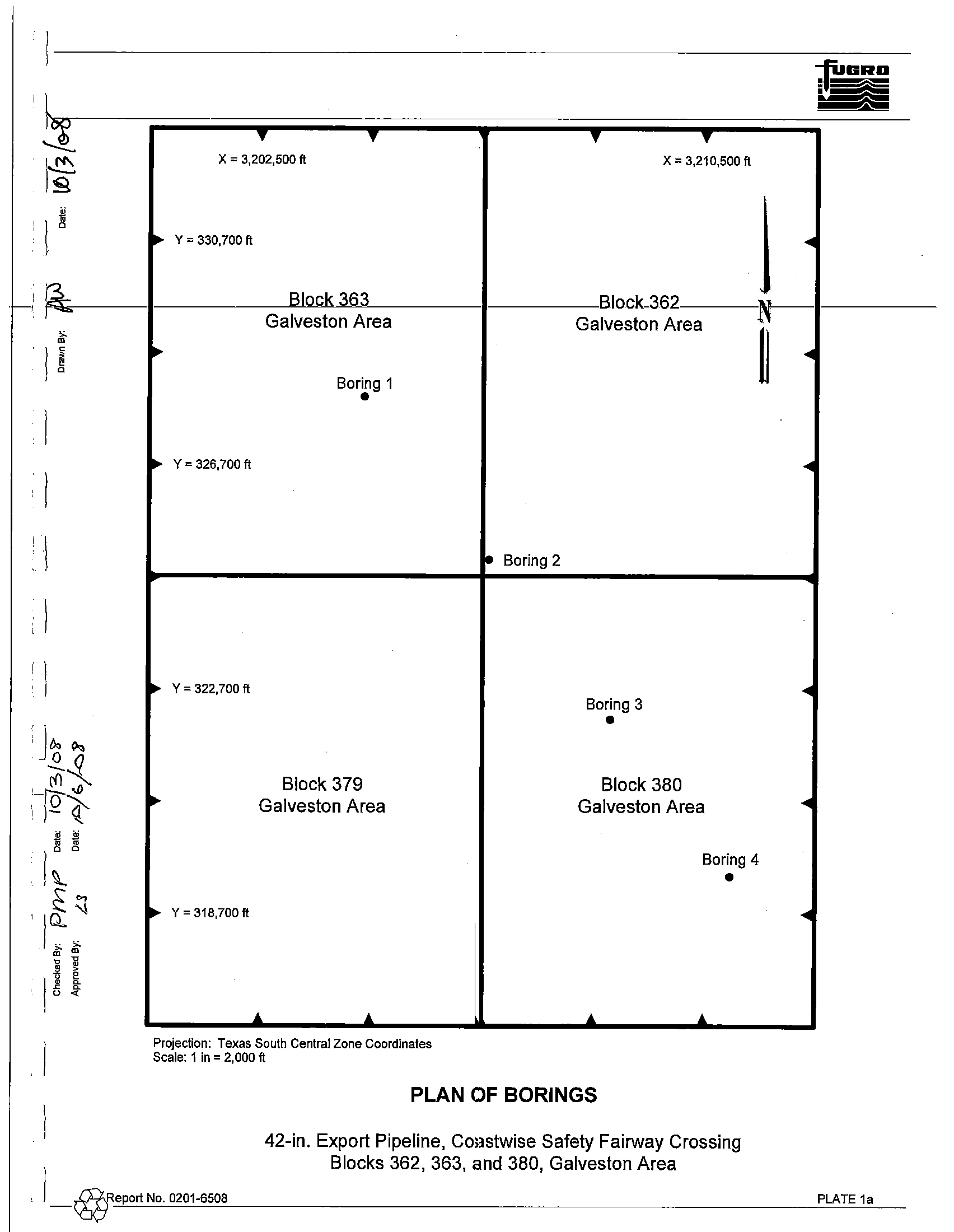
!
x
=
3,202,500 ft
~
Y
=
330,700 ft
Block 363
Galveston Area
~
Boring 1
•
~
Y
=
326,700 ft
~
Y
=
322,700 ft
Block 379
~
Galveston Area
~
Y
=
318,700 ft
J.
J.
Projection: Texas South Central Zone Coordinates
Scale: 1 in
=
2,000 ft
• Boring 2
X
=
3,210,500 ft
<II
Block_362
N-
Galveston Area
~
<II
<II
<II
Boring 3
•
Block 380
Galveston Area
<II
Boring 4
•
<II
J.
J.
PLAN OF BORINGS
) _@Report No. 0201-6508
42-in, Export Pipeline, Coastwise Safety Fairway Crossing
Blocks 362, 363, and 380, Galveston Area
PLATE 1a
1_....
I
@
;0
ro
0
"C
0
'"
Z
?
a
'"
0,
~
5
a
U>
a>
"
Date:
6:::.'1
f...:.
~
-
--
--Approvea-By:
2::::>-
--
--
--
-- --
--
--r-
--
-
,.",;p
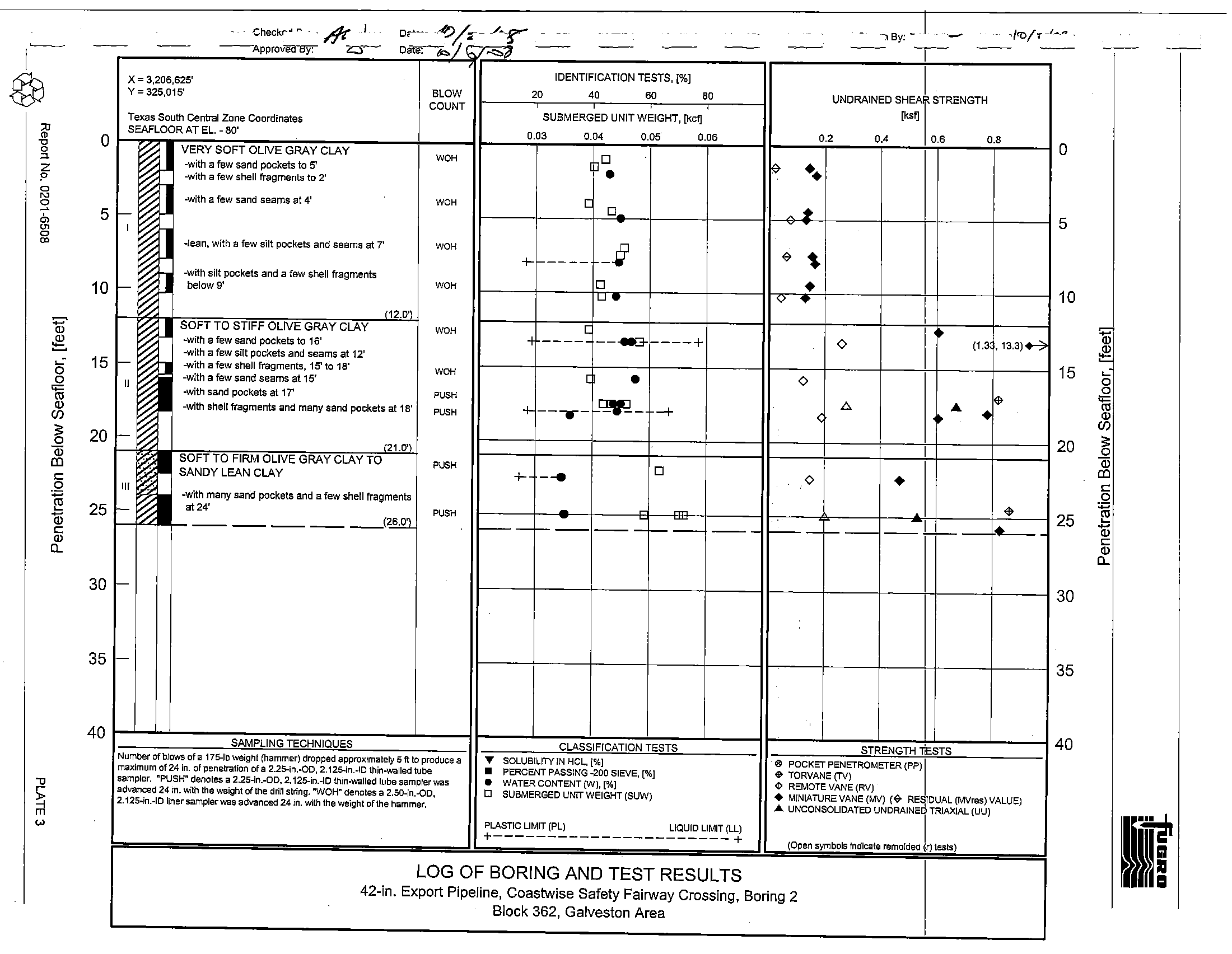
X
=
3,206,625'
IDENTIFICATION TESTS,
r;~]
I
Y=325,015'
BLOW
20
40
60
80
UNDRAINED SHEAf STRENGTH
COUNT
Iks~
Texas South Central Zane Coordinates
SUBMERGED UNIT WEIGHT,
[kcfJ
SEAFLOOR AT EL. -
80'
0.03
0.04
0.05
0.06
02
0.4
06
08
U
VERY SOFT OLIVE GRAY CLAY
WOH
0
r
-with
a few
sand pockets to 5'
•
••
-with a few shell fragments to 2'
0
-with a few sand seams at 4'
WOH
[
0
r-
..
I
0
-lean, with a few silt pockets and seams at
7'
WOH
-.v
~
~
+
----
o
5
10
15
~
...:
0
15
0
<;:
en
'"
CD
S
0
20
Qi
III
c:
0
~
Q)
25
c:
CD
CL
D
-with silt pockets and a few shell fragments
0
•
f--
below 9'
WOH
I
W•
1
<>
•
I
USOFT TO STIFF OLIVE GRAY CLAY
(12.0')
WOH
[
I
-with a few sand pockets to 16'
,13.3)+-7
,
----.
--~
---+
0
11.3
r-
-with a few silt pockets and seams at 12'
-with a few shell fragments, 15' to 18'
WOH
-with a few sand seams at 15'
I
•
0
II
-with sand pockets at 17'
~
PUSH
~-
b.
...
-with shell fragments and many sand pockets at 1S'
PUSH
+
---.--
-+
-
<
•
•
-",1.1D.
I
-
SOFT TO FIRM OLIVE GRAY CLAY TO
PUSH
0
SANDY LEft.N CLAY
+
--e
0
•
III
-with many sand pockets and a few shell fragments
c--
at 24'
<$
--------
--.(~
PUSH
-
--
--
-_.-
--
--
.-
f--
_I
1----
*---
10
J
Q)
15
~
..:
0
a
<>=
en
'"
CD
20
;;:
0
Qi
III
c:
.2
25
-
li1
c:
CD
CD
CL
30
r-
30
35
r-
35
SAMPLING TECHNIQUES
CLASSIFICATION TESTS
STRENGTH
liESTS
40
40
"
~
'"
Number of blows of a 175-lb weight (hammer) dropped approximately 5
ft
to produce a
... SOLUBILITY IN HCL,
(%]
®
POCKET PENETROMETER (PPl I
maximum of 24 In. of penetration of a 2.25-in..QD, 2.125-in.-ID thin-walled tube
•
PERCENT PASSING -200 SIEVE,
[%]
.. TORVANE (TV)
sampler. "PUSH" denotes a 225-in.-OD, 2.125-in.-ID thrn-walled lube sampler was
•
WATER CONTENT (WI,
[%]
¢o
REMOTE VANE (RV)
advanced 24 rn. with the weight of the drill siring. "WOH" denotes a 2.S0-in..QD,
0
SUBMERGED UNIT WEIGHT (SUW)
•
MINIATURE VANE (MV)
(~
RESIDUAL (MVres) VALUE)
2.125-in.-ID liner sampler was advanced 24 rn. with the weight of the hammer.
... UNCONSOLIDATED UNDRAINED TRIAXIAL (UU)
PLASTIC LIMIT (PL)
LIQUID LIMIT (LL)
I
+----------------------+
(Open symbols indicate remolded
~r)
lests)
LOG OF BORING AND TEST RESULTS
42.in. Export Pipeline, Coastwise Safety Fairway Crossing, Boring 2
Block 362, Galveston Area
~
~
r;,o
~
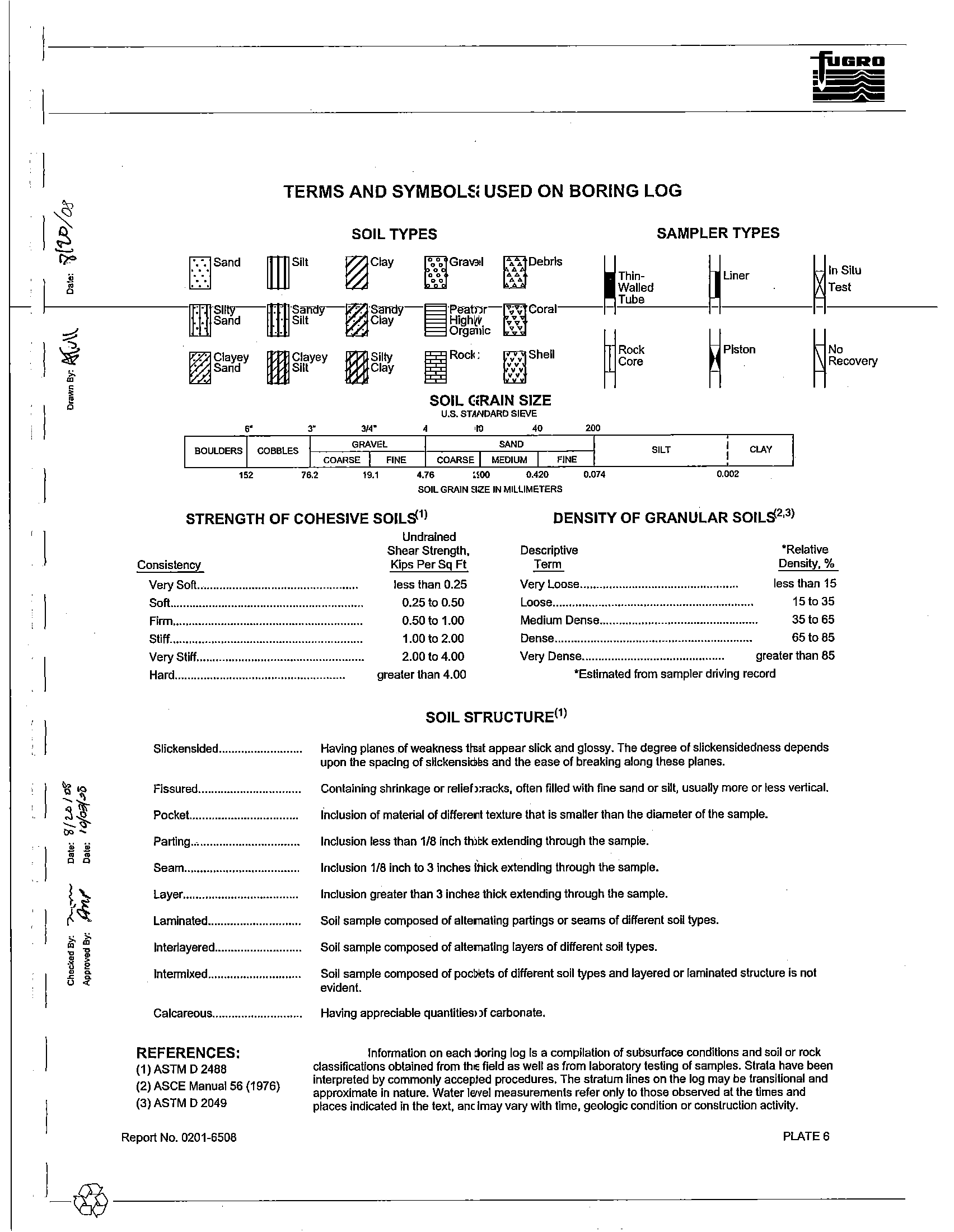
TERMS AND SYMBOLS USED ON BORING LOG
SOIL TYPES
SAMPLER TYPES
" "
°
0
°
0
...,..:....
Thin-
Liner
.•.
Walled
D
..:..
Sand
m
Sllt
~Clay
'.:0 Gravel
~.,
Debris
~
~
Tube
f---------mSIIV--fIT(] S"""v-I!%! Sam:lY-a
P"ator- •••• Coral--- -
--
lJ::j]
Sand
IillI
Slit
~
Clay
B
~%~%c
.:..
~
~
~lnSiLU
~Test
~
~
liJ
J
, 1
II
'\!'"
","
I
~
;3
;; ..
('3;.
I}
~~
~
•
1
•
~
Q
U
:t
~Ciayey
mCJayey
mSiity
~Rock
fmShel1
§~~~
Piston
~Sand
m
S11t
Welay
~
~
~NO
~ReCOVery
SOIL GRAIN SIZE
u.s. STANDARD SIEVE
3.
~,.
,.
,.
2••
COBBLES
GRAVEL
SAND
SILT
CLAY
COARSE
FINE
COARSE I
MEDIUM
FINE
152
76.2
19.1
4.76
2.00
0.420
0.074
0.002
SOIL GRAIN SIZE IN MILLIMETERS
STRENGTH OF COHESIVE SOILS')
Undrained
DENSITY OF GRANULAR SOILS
2•3)
Consistency
Shear Strength,
Kips Per Sq Ft
Descriptive
Term
*Relative
Density, %
Very Soft........................................
less than 0.25
0.25 to 0.50
0.50
to 1.00
Very Loose ................................................ less than 15
Soft............................................................
Loose........•.•.........•.........................................
15t035
Firm.•.........................................................
Medium Dens6.................................................
35 to 65
Stiff............................................................
1.00 to 2.00
Dense.............................................................
65
to
85
Very
Stiff....................................................
2.00 to 4.00
Very Oens9............................................
greater than
85
Hard.....................................................
greater than 4.00
"Estimated from sampler driving record
Slickensided ..........................
Fissured................................
Pocket..................................
Parting
..-................................
Seam....•••..........•..................
Layer.•..•......••..•........•...........
Laminated..............•..........•...
Interlayered...........................
Intermixed......•....•........••.•.•...
Calcareous............................
REFERENCES:
(1) ASTM D 2488
(2)
ASCE Manual 56 (1976)
(3)
ASTM D 2049
Report No. 0201-6508
SOIL STRUCTURE(')
Having planes of weakness that appear slick and glossy. The degree of slickensidedness depends
upon the spacing
of slickensides and the ease of breaking along these planes.
Containing shrinkage
or relief cracks, often filled with fine sand or silt, usually more or less vertical.
Inclusion
of material of different texture that is smaller than the diameter of the sample.
Inclusion less
than 1/8 inch thick extending through the sample.
Inclusion 1/8 inch to 3 inches thick extending through
the sample.
Inclusion greater than 3 inches thick extending through the sample.
Soil sampte composed
of alternating partings or seams of different soil types.
Soil sample composed
of alternating layers of different soH types.
Soil sample composed
of pockets of different soil types and layered or laminated structure Is not
evident.
Having appreciable quantities of carbonate.
Infonnation on each boring log
[s a compilation of subsurface conditions and sailor rock
classifications obtained from the field as well as
from laboratory testing of samples. Sirata have been
interpreted
by commonly accepted procedures. The stratum lines on the log may be transitional and
approximate in nature.
Water level measurements refer only to those observed at the times and
places indicated in the text. and
may vary with time, geologic condition or construction activity.
PLATE 6
-
-
-
-_..
- -
-
-
-
-- --
-
-
---
-
--
--L
---
--
~~
--
--
~
--
~--
--
--
-
-- --
--
--
-I
Checked By: Ift-0
Date:
p/2!-~~
Drawn
By:
'?"I---
Date:/
o/Z,Id8"
~
Approved
By:
LS
Date:
("""j
~
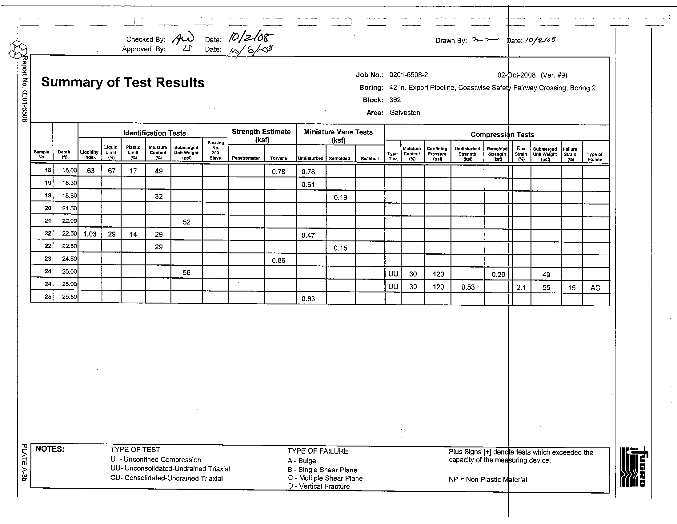
0201-6508-2
02toct-2008 (Ver. #9)
ro
'C
0
Job No.:
"
z
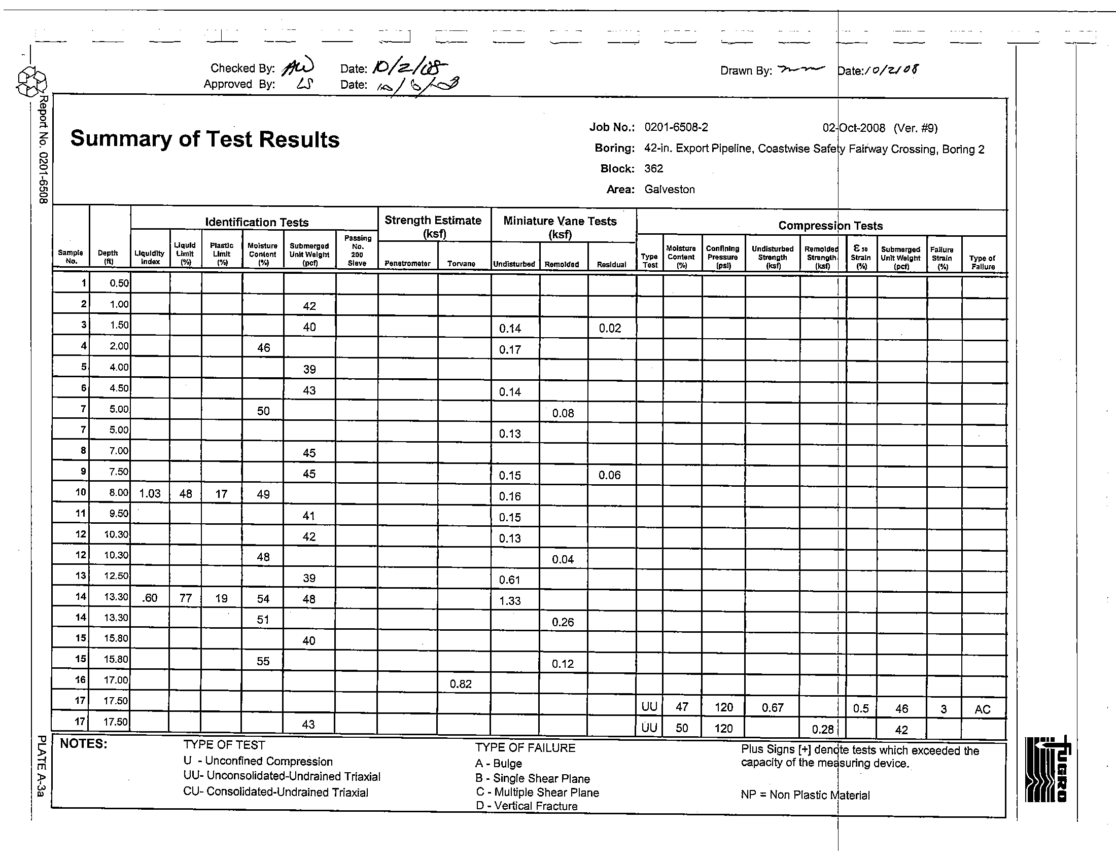
Summary of Test Results
42-in. Export Pipeline, Coastwise Safe
y
Fairway Crossing, Boring 2
0
Boring:
0
'"
Block:
362
~
0,
Area:
Galveston
'"
0
'"
Identification Tests
Strength Estimate
Miniature Vane Tests
compreSSi~n
Tests
Passing
(ksf)
(ksf)
I
Uquld
PlaErtlc
Mgjstul1I
Submerged
N,.
Moisture
Connnlnll
Undisturbed
RemOlde~
E..
Submerged
Failure
Sample
Deptll
Liquidity
limIt
Limit
Content
Unit Weight
'"
,.".
Content
Pressure
S~~~th
strength
Slr.I.[n
Unit Weight
Strain
Type of
N,.
1ft)
Index
(%)
)%)
(o!.)
,po"
Sieve
Penetrometer
Torvane
Undisturbed
RemOlded
Residual
Test
(%)
(psl)
("'"
(%)
(,d)
(%)
Failure
1
0.50
1
2
1.00
42
1
3
1.50
40
0.14
0.02
1
4
2.00
46
0.17
1
5
4.00
39
1
6
4.50
43
0.14
1
7
5.00
50
0.08
1
7
5.00
0.13
1
8
7.00
45
1
9
7.50
45
0.15
0.06
1
10
8.00
1.03
48
17
49
0.16
1
11
9.50
.
41
0.15
1
12
10.30
42
0.13
1
12
10.30
48
0.04
1
13
12.50
39
0.61
1
14
13.30
.60
77
19
54
48
1.33
1
14
13.30
51
0.26
1
15
15.80
40
1
15
15.80
55
0.12
1
16
17.00
0.82
1
17
17.50
UU
47
120
0.67
1
0.5
46
3
AC
17
17.50
43
UU
50
120
0.281
42
"Cl
NOTES:
TYPE OF TEST
TYPE OF FAILURE
Plus Signs [+] den9te tests which exceeded tile
If
S;
-!
U
- Unconfined Compression
A - Bulge
capacity of the merUring device.
m
:po
UU- Unconsolidated-Undrained Triaxial
B
- Single Shear Plane
'"
CU- Consolidated-Undrained Triaxial
C - Multiple Shear Plane
NP ::;; Non Plastic Material
w
I
D
- Vertical Fracture
---
-
-
I
~
i
z
?
o
~
~
'"
S
"
m
~
"~
~--'
CO"
--
,
-
""'/ --/.
-
Job No.:
Summary of Test Results
Boring:
Block:
Area:
Identification Tests
Strength Estimate
Miniature Vane Tests
Passing
(ksf)
(ksf)
Liquid
Plasllc
Moisture
Submerged
N,.
Sample
Depth
Liquidity
Limit
Limit
Content
UnltWelglil
'"'
No.
,ft,
Indel(
("10)
("10)
,%,
(pef)
Sieve
Penetrometer
TOrvall8
UndlstuTbed
Remolded
Residual
,.
18.00
.63
67
17
49
0.78
0.78
1.
18.30
0.61
1.
18.30
32
0.19
20
21.50
.
21
22.00
52
22
22.50
1.03
29
14
29
0.47
22
22.50
29
0.15
23
24.50
0.86
24
25.00
56
24
25.00
25
25.80
0.83
NOTES:
TYPE OF TEST
TYPE OF FAILURE
U - Unconfined Compression
A- Bulge
UU- Unconsolidated-Undrained Triaxial
B - Single Shear Plane
CU- Consolidated-Undrained Triaxial
C - Multiple Shear Plane
0_ - Vertical Fracture
F
la/va
If
,
0201-6508-2
02-
~ct-2008
(Ver. #9)
42-in. Export Pipeline, Coastwise Safet
Fairway Crossing, Boring 2
362
Galveston
compreSSi~n
Tests
Moisture
Confining
Undisturbed
Remolded
8"
Submerged
Fanure
Type
Content
Prenuni
Strength
Strength
Str:aln
Unit Weight
Sualn
Typa of
Test
{%'
(psi)
,"'"
...
('10)
'pol}
,%,
Failure
I
I
I
UU
30
120
0.20 I
49
UU
30
120
0.53
2.1
55
15
AC
I
'""...,., 00,+ _""" _,0.,
capacity of the me uring device.
NP
= Non Plastic
terial
i
1
, 1
i
1
-I
Back to top
TOPs.,
Texas Dtlshore Port Syslem
SOIL BORINGS
CORES
1-4
GALVESTON AREA BLOCKS 362, 363 & 380
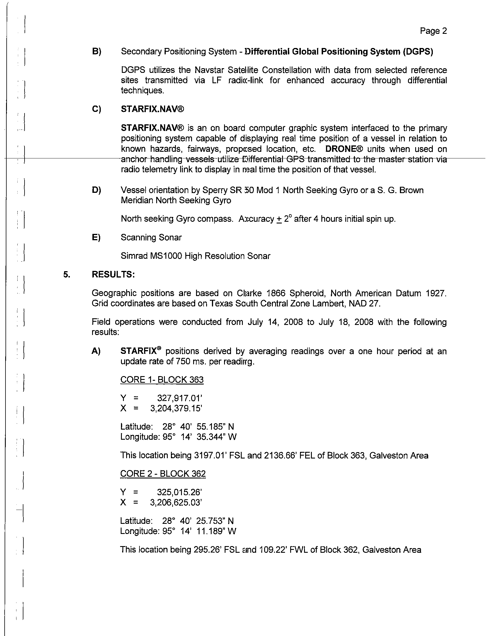
1.
INTRODUCTION:
Fugro Chance Inc. (CHANCE)
was contracted by Fugro-McClelland Marine Geosciences,
Inc.
to position the UB
"Petite"
for soil borings and to perform pre-well site investigations in
Galveston Area, Blocks 362, 363 and 380, Offshore Texas.
2.
REQUIREMENTS:
Positioning requirements were transmitted,
via e-mail, to Mr. Tony Parker of
CHANCE
by Mr.
Frank Ortiz of Fugro-McClelland Marine Geosciences, Inc. "Survey Request" forms dated
July
10, 2008 e-mailed to Mr. Manuel Lopez of Enterprise Field Services, L.L.C., confirmed
these requirements. Copies of these forms were also e-mailed to
Mr. Frank Ortiz.
Requirements were as follows:
A)
Proposed Locations
The Texas South Central Zone Coordinates are:
CORE 1- BLOCK 363
Y
=
327,915.88'
X
= 3,204,371.92'
CORE 3 - BLOCK 380
Y
=
322,163.06'
X
=
3,208,819.93'
CORE 2 - BLOCK 362
Y
=
325,019.26'
X
= 3,206,611.55'
CORE 4 - BLOCK 380
Y
=
319,372.40'
X
= 3,210,977.64'
B)
Utilize scanning Sonar to perform site investigations.
3.
CHANCE PERSONNEL:
4.
Party Chief
-
P. Arceneaux
Surveyor
- W. Straton
EQUIPMENT AND METHOD:
A)
Primary Positioning System - STARFIX" Satellite
Positioning System
Continuous dynamic positioning through the use of Navstar GPS with differential
signals from multiple reference stations corrected for ionospheric
and tropospheric
effects transmitted via the STARFIX" equatorial geosynchronous satellite.
1
Page 2
B)
Secondary Positioning System - Differential Global
Positioning System (DGPS)
DGPS utilizes the Navstar Satellite Constellation with data from selected reference
sites transmitted via
LF radio-link for enhanced accuracy through differential
techniques.
C)
STARFIX.NAV®
STARFIX.NAV® is an
on board computer graphic system interfaced to the primary
positioning system capable of displaying
real time position of a vessel in relation to
known hazards, fairways, proposed location, etc.
DRONE® units when used
on
+-...,--j--------~anchor_handling-vessels-lJtilize-f)ifferential-ePs-transmittedio-the-master-station-vi""a---
radio telemetry link to display in real time the position of that vessel.
I
1
i
I
!
1
-I
1
, I
D)
E)
Vessel orientation by Sperry SR 50 Mod 1 North Seeking Gyro or a S. G. Brown
Meridian North Seeking Gyro
North seeking Gyro compass. Accuracy:!::
2° after 4 hours initial spin up.
Scanning Sonar
Simrad MS1000 High Resolution Sonar
5.
RESULTS:
Geographic positions are based
on Clarke 1866 Spheroid, North American Datum 1927.
Grid coordinates are based on Texas South Central Zone Lambert, NAD 27.
Field operations were conducted from July
14, 2008 to July 18, 2008 with the following
results:
A)
STARFIX'" positions derived by averaging readings over a one hour period at
an
update rate of 750 ms. per reading.
CORE 1- BLOCK 363
Y
=
327,917.01'
X =
3,204,379.15'
Latitude:
28° 40' 55.185" N
Longitude: 95° 14' 35.344" W
This location being 3197.01' FSL and 2136.66' FEL
of Block 363, Galveston Area
CORE 2 - BLOCK 362
Y
=
325,015.26'
X =
3,206,625.03'
Latitude:
28° 40' 25.753" N
Longitude: 95° 14' 11.189" W
This location being 295.26' FSL and 109.22' FWL of Block 362, Galveston Area
I J
:l
I J
I
I
CORE 3 - BLOCK 380
Y
=
322,164.00'
X
=
3,208,821.22'
Latitude:
28° 39' 56.835" N
Longitude: 95° 13' 47.578" W
Page 3
This location being 2556.00' FNL and 2305.41'
FWL of Block 380, Galveston Area
CORE 4 - BLOCK 380
319,368.63
X
=
3,210,976.70'
Latitude:
28° 39' 28.482" N
Longitude: 95° 13' 24.406" W
This location being 5351.37' FNL and 4460.89'
FWL of Block 380, Galveston Area
6.
CONFIRMATION:
7.
8.
DGPS was used for confirmation.
The results were as follows:
CORE 1 - BLOCK 363
Y
=
327,917'
X
= 3,204,379'
CORE 3 - BLOCK 380
Y
=
322,164'
X
= 3,208,821'
HSE INCIDENTS:
No incidents.
CHRONOLOGY:
July 14, 2008
CORE 2 - BLOCK 362
Y
=
325,015'
X
= 3,206,625'
CORE 4 - BLOCK 380
Y
=
319,369'
X
= 3,210,977'
0700 Arrived at Lafayette office to pick up
job packet and equipment, departing for Pelican
Island; start time for job
1300 Arrived at dock; mobing
UB "Petite"
1600 Mob complete; standing by to depart for proposed location
1830
En route to location GA. 363